Gas generator and assembling method of the same

a gas generator and assembling method technology, applied in the direction of manufacturing tools, pedestrian/occupant safety arrangements, vehicular safety arrangements, etc., can solve the problems of insufficient ability to ignite the gas generating agent b>, and cannot be secured

Active Publication Date: 2012-11-06
DAICEL CHEM IND LTD
View PDF15 Cites 9 Cited by
  • Summary
  • Abstract
  • Description
  • Claims
  • Application Information

AI Technical Summary

Problems solved by technology

Therefore, a sufficient ability to ignite the gas generating agent 16 cannot be secured, leaving room for improvement.

Method used


Image

  • Gas generator and assembling method of the same
  • Gas generator and assembling method of the same
  • Gas generator and assembling method of the same

Examples


Embodiment Construction

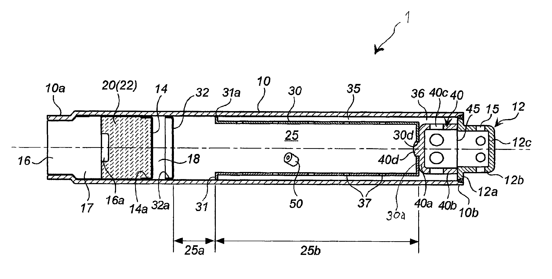
[0039]The present invention provides an elongated gas generator with an improved ability to ignite a whole gas generating agent regardless of an installation condition of the gas generator in a vehicle.

[0040]The ignition device is a combination of a known electric igniter and a known transfer charge or gas generating agent, and is mounted in the side of one end of the tubular housing.

[0041]The diffuser portion may be one used in a known inflator and is favorably a cup-shaped diffuser portion having a flange at an opening portion and having a plurality of gas discharge ports on a peripheral wall surface. The diffuser portion is mounted in the side of the other end of the tubular housing.

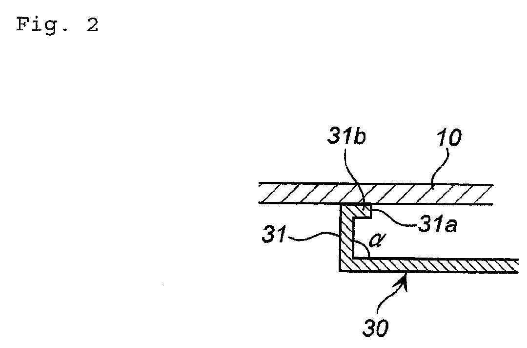
[0042]The first combustion chamber is a space formed by the first perforated-plate member disposed in the tubular housing, the tubular housing, and an igniter (or a collar that fixes the igniter), and is filled with the first gas generating agent.

[0043]The first combustion chamber is formed by dividin...


PUM

PropertyMeasurementUnit
thicknessaaaaaaaaaa
outer diameteraaaaaaaaaa
combustion temperatureaaaaaaaaaa

Abstract

The present invention provides a gas generator, including:a tubular housing, an ignition device attached to one end of the tubular housing, a diffuser portion having a gas discharge port and being attached to the other end of the tubular housing,in the tubular housing,a first combustion chamber defined by a first perforated-plate member on one end side in the tubular housing and filled with a first gas generating agent,a tubular member disposed in the remaining inner space of the tubular housing and having a communication hole on a peripheral wall portion thereof, a second-perforated plate member disposed between the first perforated-plate member and the tubular member, a second combustion chamber defined by the tubular member and filled with a second gas generating agent,the tubular member being disposed so that a gap is formed between the peripheral wall portion of the tubular housing and the tubular member, the tubular member having a first opening end portion abutting against the inner peripheral surface of the tubular housing in the side of the first perforated-plate member and a second end portion supported in the side of the diffuser portion.

Description

[0001]This nonprovisional application claims priority under 35 U.S.C. §119 (a) to Patent Application No. 2010-21863 filed in Japan on 3 Feb. 2010 and 35 U.S.C. §119(e) to U.S. Provisional Application No. 61 / 301,442 filed on 4 Feb. 2010, both of which are incorporated by reference.BACKGROUND OF THE INVENTION[0002]1. Field of the Invention[0003]The present invention relates to a gas generator used in a restraining device in a vehicle and the like such as an air bag device, and more particularly to a gas generator used in an air bag system for deploying an air bag in the lateral side of an occupant.[0004]2. Description of Related Arts[0005]A gas generator used in a device that deploys the air bag in the lateral side of the occupant is often formed in an elongated cylindrical shape because of the place where the gas generator is attached. A cylindrical housing is disposed inside a vehicle in the substantially vertical direction or the horizontal direction.[0006]US-A, No. 2008 / 0078486 di...

Claims


Application Information

Patent Timeline
Patent Type & Authority Patents(United States)
IPC IPC(8): B60R21/261B60R21/263B60R21/264
CPCB60R21/262B60R21/2644Y10T29/49863B60R2021/2648B60R21/264B60R2021/26011
Inventor HANANO, TEPPEIYAMAZAKI, MASAYUKI
Owner DAICEL CHEM IND LTD
Why Eureka
Try Eureka