Soap bar or substance application bar

a soap bar and substance technology, applied in the field of substance application bars, can solve the problems of difficult to grasp firmly with the hands, add to the difficulty and expense of manufacturing, and the surface of soap bars is often extremely slippery, so as to avoid waste and easy to grasp firmly without slipping

Active Publication Date: 2012-11-06
4MULA
View PDF32 Cites 13 Cited by
  • Summary
  • Abstract
  • Description
  • Claims
  • Application Information

AI Technical Summary

Benefits of technology

[0018]The present invention relates to a substance application bar, which is typically designed to be easy to grasp firmly without slipping and to avoid waste due to prolonged exposure to liquids. The substance application bar preferably includes an application portion having an exterior surface and an interior surface, and is configured for applying a substance to a receiving surface and at least one blocking extension extending adjacent the interior surface of the application portion to define a retaining recess therebetween. The blocking extension and the interior surface are advantageously associated to cooperatively substantially block movement of an object received in the retaining recess in a direction generally along the interior surface against the blocking extension.
[0025]The present invention also relates to a substance application bar, which includes an application portion having an exterior surface and an interior surface made of a substance that can deteriorate when exposed to a fluid and configured for applying a substance to a receiving surface. The substance application bar also includes at least one bar-preserving extension extending adjacent the interior surface of the application portion to define an open recess therebetween. The bar-preserving extension and the recess are configured to maintain a portion of the recess open to the atmosphere to facilitate air flow through, and for drying of, the recess for resisting deterioration of the bar. In a preferred embodiment, the substance is soap. Typically, the application portion is made of the substance.

Problems solved by technology

A significant disadvantage associated with the prior art soap bars is that the surfaces of the soap bars are often extremely slippery and may be hard to grasp firmly with the hands.
It can be very frustrating to have to search for and pick up the soap that has slipped from one's hand into the bath tub when one is bathing or showering.
First of all, the requirement of a second material in addition to soap adds to the difficulty and expense of manufacturing.
Secondly, the additional material may not be resistant to the high temperature treatment entailed when the soap mixture is poured into the mold.
Lastly, since an extraneous structure is included in the soap bar, it might fall off when a portion of the soap is inevitably eroded.
Firstly, the irregular shape of the soap bar makes it more difficult to pack, transport and store.
Secondly, this design puts too much strain on the little finger, which is of course, typically the smallest and weakest finger on someone's hand.
Lastly, the addition of a projecting member off the soap bar makes it aesthetically less appealing to users.
Another well recognized disadvantage of soap bars is the deterioration which the soap undergoes when it is left in a soap holder.
If the soap is not dried quickly after it is put in a soap holder the surface of the soap will frequently soften and erode away.
This results in undue waste and a much shorter lifespan of the cake soap or soap bar.
The problem is even more acute when, for example, the container used to hold the soap does not have holes at the bottom to drain water that may be retained on the surface of the soap.
Another factor that increases the waste occurs when a large area of the soap container's bottom touches the soap, thus preventing the ventilation and drying of the soap.
Although these soap bar holders provide better ventilation, and thus faster drying of the soap bars, they may nevertheless shorten the lifespan of the soap by effecting a cut in the soap bar with the rib and the cords.
Moreover, since all the above designs focus on the holder or case of the soap bars in order to preserve the soaps, they do not afford improvement in the soap bars themselves to achieve the preservation.
One obvious disadvantage of this design is that when the soap is provided from a heated mixture into the mold, the material for the base portion might not be able to withstand the heat.
The inclusion of another material in addition to the soap mixture will also raise the manufacturing cost of the soap bars.
The bar is not designed for easy handling and does not address the problem of waste associated with prolonged exposure to fluids.
These containers have not satisfactorily solved the above-mentioned problems because they do not aid in the grasping of the soap bar.
Moreover, they do not provide the versatility of an application bar that may act as packaging, soap dish or the soap itself.

Method used


Image

  • Soap bar or substance application bar
  • Soap bar or substance application bar
  • Soap bar or substance application bar

Examples


example 1

An Assembly of Substance Application Bars According to the Invention

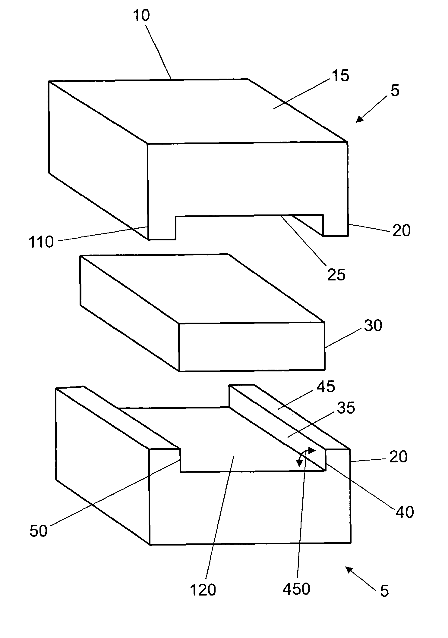
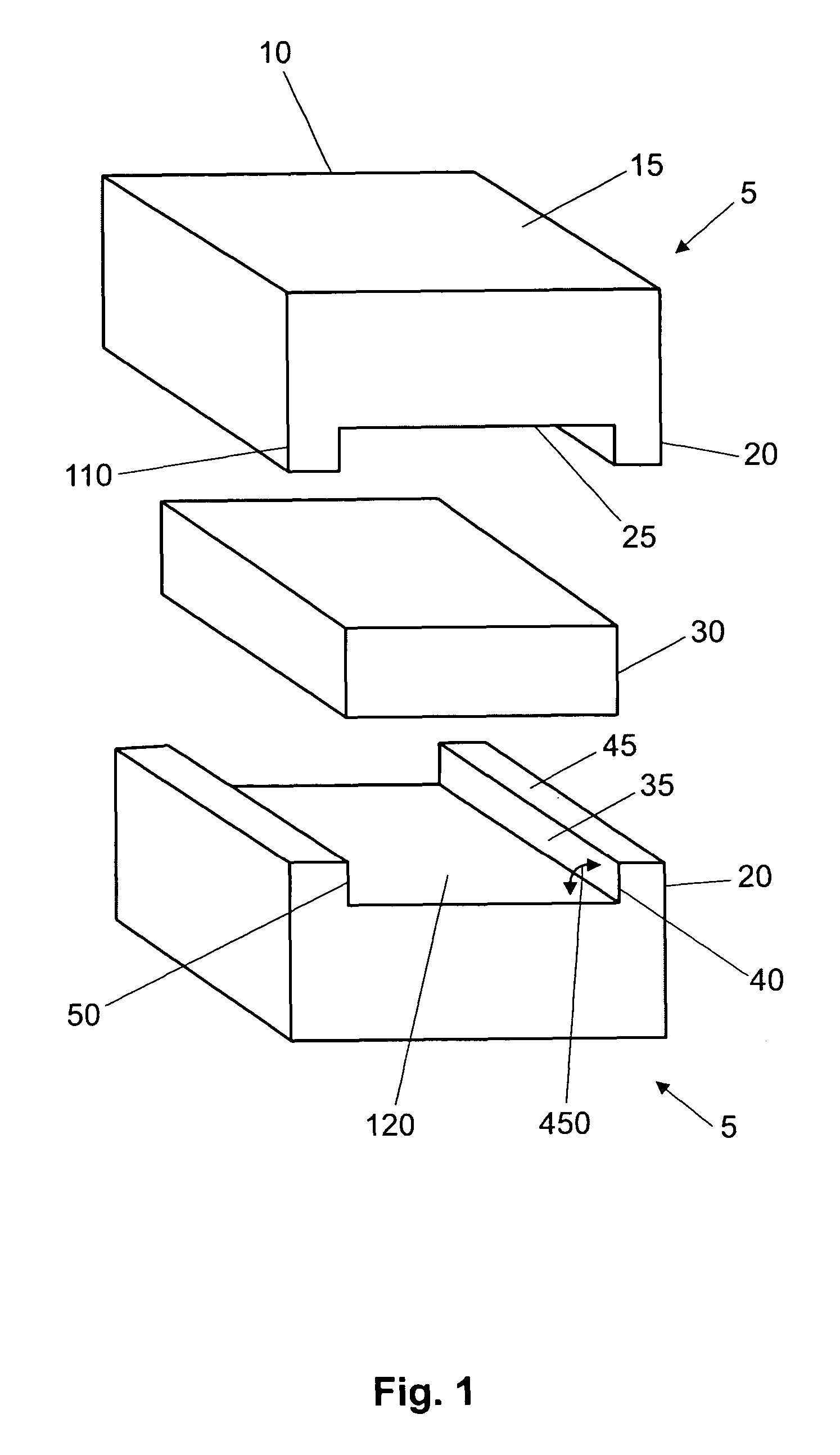
[0068]The accompanying FIG. 9 illustrates an exemplary assembly of substance application bars constructed according to the present invention. Substance application bars 205, 210 were formed from a combination of saponified (olive, castor, palm and coconut) oils, vegetable glycerin, soybean oil, essential oils, and FD&C color. Edges 300 and 310 define surface 500 of application bar 205. Surface 500 was made to measure about 3 inches in length and 3 inches in width. Edges 300, 320, 330, 340, and 370 define surface 520. Edge 300 was made to measure about 3 inches in length. Edge 320 was made to measure about 1 7 / 16 inches, making the whole assembly about 2⅞ inches in height. Edge 330 was made to measure about ⅜ of an inch in length, while edge 340 was made to measure about 2¼ inches in length. Edge 370 was made to measure about 1 inch in height. The bar 240 was formed from a combination of saponified (olive, castor, pa...


PUM

PropertyMeasurementUnit
angleaaaaaaaaaa
heightaaaaaaaaaa
angleaaaaaaaaaa

Abstract

The substance application bar includes an application portion having an exterior surface and an interior surface and configured for applying a substance to a receiving surface and at least one blocking extension extending adjacent the interior surface of the application portion to define a retaining recess therebetween. The blocking extension and the interior surface are associated to cooperatively substantially block movement of an object received in the retaining recess in a direction generally along the interior surface against the blocking extension. The substance application bar may also include at least one bar-preserving extension associated with the interior surface to maintain a portion of the recess open to the atmosphere. This facilitates air flow through and drying of the recess for resisting deterioration of the bar. An assembly of application bars in stacked association also is included.

Description

FIELD OF INVENTION[0001]The present invention relates to a substance application bar that includes a blocking extension or a bar-preserving extension. It further relates to an assembly of application bars in stacked association.BACKGROUND ART[0002]Many different forms of application bars, such as soap bars, have been described in the prior art. A significant disadvantage associated with the prior art soap bars is that the surfaces of the soap bars are often extremely slippery and may be hard to grasp firmly with the hands. It can be very frustrating to have to search for and pick up the soap that has slipped from one's hand into the bath tub when one is bathing or showering. Furthermore, it is desirable that the soap bar can be grasped by the user in such a fashion that the user may manipulate the soap bar in a brushing fashion having the largest flat area of the soap placed in physical contact with the body surface to be lathered.[0003]U.S. Pat. No. 4,618,443 discloses a soap bar s...

Claims


Application Information

Patent Timeline
Patent Type & Authority Patents(United States)
IPC IPC(8): A45D40/20A47K5/08C11D13/14C11D17/00
CPCA47K5/08C11D13/14C11D17/0047
Inventor BAHASH, TIMOTHY J.
Owner 4MULA
Why Eureka
Try Eureka