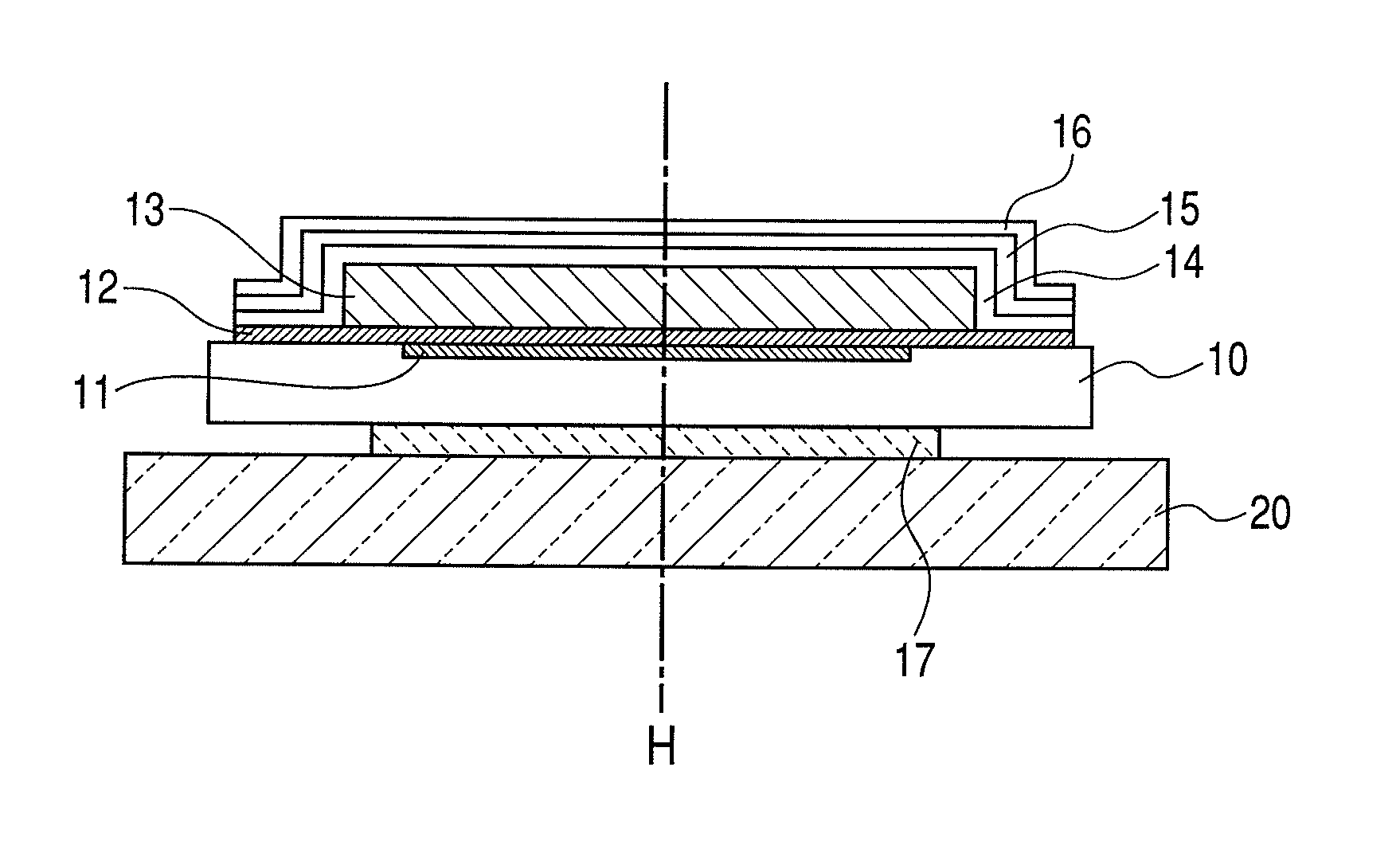
Radiation detecting apparatus and radiation detecting system

a radiation detection and apparatus technology, applied in the direction of radiation intensity measurement, instruments, x/gamma/cosmic radiation measurement, etc., can solve the problems of already generated stresses in use environments, high possibility of peeling or breakage at the corner portion to which large stress is applied, etc., to prevent light intensity degrading and resolution degrading, and reduce the peeling of the scintillator layer

Active Publication Date: 2012-11-06
CANON KK
View PDF42 Cites 18 Cited by
  • Summary
  • Abstract
  • Description
  • Claims
  • Application Information

AI Technical Summary

Benefits of technology

[0009]In view of the foregoing problems, it is an object of the present invention to provide a radiation detecting apparatus capable of reducing peeling between an array substrate and a scintillator layer, caused by a difference in coefficients of thermal expansion between members.
[0015]The present invention can reduce peeling of the scintillator layer of the radiation detecting apparatus and can prevent light intensity degrading and resolution degrading.

Problems solved by technology

However, the conventional technologies described above cause the following problems: the protective film, the scintillator layer, the photoelectric conversion element substrate and the adhesive agent for joining the base have different coefficients of thermal expansion from each other, so that stress is generated at each portion by surrounding environment temperature and heat generation inside the apparatus.
Particularly, a large temperature difference between manufacturing processes for forming respective members has already generated stresses under use environments of apparatuses.
In particular, there is a high possibility of peeling or breakage at a corner portion to which large stress is applied.

Method used


Image

  • Radiation detecting apparatus and radiation detecting system
  • Radiation detecting apparatus and radiation detecting system
  • Radiation detecting apparatus and radiation detecting system

Examples


applied example

[0062]Referring next to FIG. 12, description will be made of an applied example where the radiation detecting apparatus according to the embodiment of the present invention is applied to a radiation detecting system as an image diagnostic system.

[0063]The radiation 1002 generated at a radiation tube (radiation source) 1001 passes through a portion 1004 of the body, such as the chest of a person to be inspected 1003 like a patient and enters a radiation imaging apparatus 1100 with a scintillator mounted on the top thereof. The incident radiation 1002 includes information of the internal body of the person to be inspected 1003. In the radiation imaging apparatus 1100, the scintillator illuminates in response to the incidence of radiation 1002, which is subjected to photoelectric conversion to obtain electrical information. In addition, the radiation imaging apparatus 1100 may convert radiation 1002 directly into charges to obtain electrical information. The electrical information is c...


PUM


Abstract

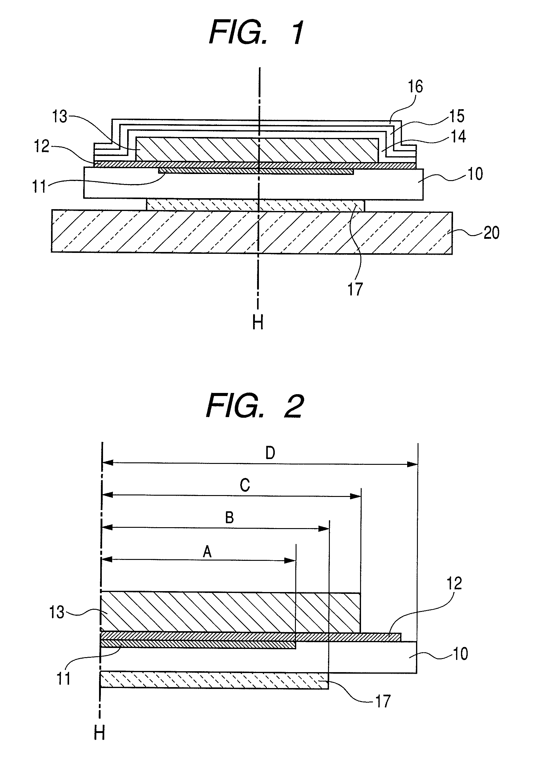
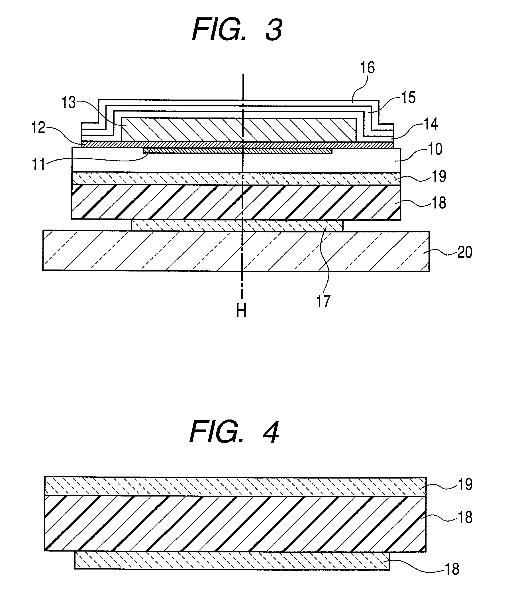
To reduce peeling between members constituting an radiation detecting apparatus, the radiation detecting apparatus of the present invention includes a laminating layered structure in which a supporting substance, an adhesive layer, an array substrate having a photoelectric conversion element, a scintillator layer for converting a radiation into light and a resin layer are stacked in this order. Of arrangement regions of each layer in a plane direction, an arrangement region of the scintillator layer is broader than the region opposed to a photoelectric conversion element, and an arrangement region of the adhesive layer is the same as or broader than the arrangement region of the photoelectric conversion element and at least a portion of the arrangement region of the adhesive layer is narrower than that of the scintillator layer.

Description

TECHNICAL FIELD[0001]The present invention relates to a radiation detecting apparatus and a radiation detecting system and, in particular, a radiation detecting apparatus and a radiation detecting system used for radiography and the like.BACKGROUND ART[0002]Conventionally, a radiation detecting apparatus including a radiation film having a radiation intensifying screen and a photosensitive layer having a scintillator layer for converting X-rays into light has been generally used in radiographing.[0003]However, there has been recently developed a digital radiation detecting apparatus having a scintillator having a scintillator layer and a two-dimensional photo detector having a photoelectric conversion element. In the digital radiation detecting apparatus, since data obtained is digital data, image processing is easily performed. Accordingly, by incorporating such digital radiation detecting apparatus into a networked computer system, the data can be shared. In addition, there is the...

Claims


Application Information

Patent Timeline
Patent Type & Authority Patents(United States)
IPC IPC(8): G01J5/28
CPCG01T1/20G01T1/2018G01T1/2928
Inventor INOUE, MASATOOKADA, SATOSHITAKEDA, SHINICHINAGANO, KAZUMINOMURA, KEIICHISAWADA, SATORU
Owner CANON KK
Why Eureka
Try Eureka