Fluid delivery substrates for building removable standard fluid delivery sticks

a technology of fluid delivery substrate and standard fluid, which is applied in the direction of valve housing, transportation and packaging, mechanical equipment, etc., can solve the problem of not being able to remove a single gas stick intact from the gas panel

Active Publication Date: 2012-11-13
COMPART SYST PTE LTD
View PDF171 Cites 32 Cited by
  • Summary
  • Abstract
  • Description
  • Claims
  • Application Information

AI Technical Summary

Benefits of technology

[0011]Embodiments of the present inventive flow substrate and standard stick bracket designs minimize the total number of fluid conduit ports and seals needed to build standardized fluid delivery sticks. Each flow substrate has a component attachment surface with one or more component conduit ports and an associated plurality of fastener apertures. Some flow substrates incorporate a transverse manifold connection conduit port on a surface opposite the comp...

Problems solved by technology

In these designs it is not feasible to remove a single gas stick intact from the gas panel because one or more active components must first be removed to allow access to the fasteners which couple together the first and second...

Method used


Image

  • Fluid delivery substrates for building removable standard fluid delivery sticks
  • Fluid delivery substrates for building removable standard fluid delivery sticks
  • Fluid delivery substrates for building removable standard fluid delivery sticks

Examples


first embodiment

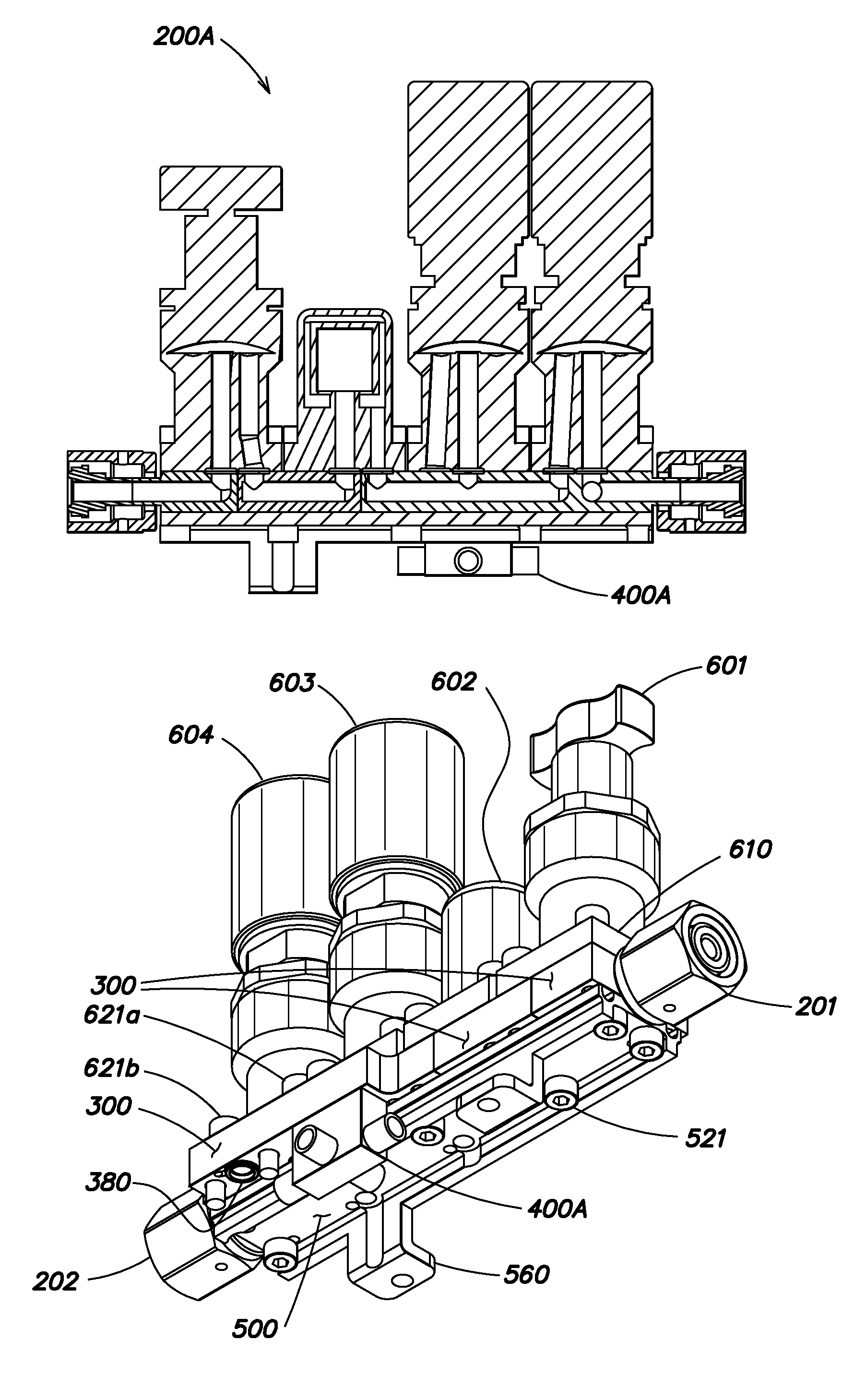
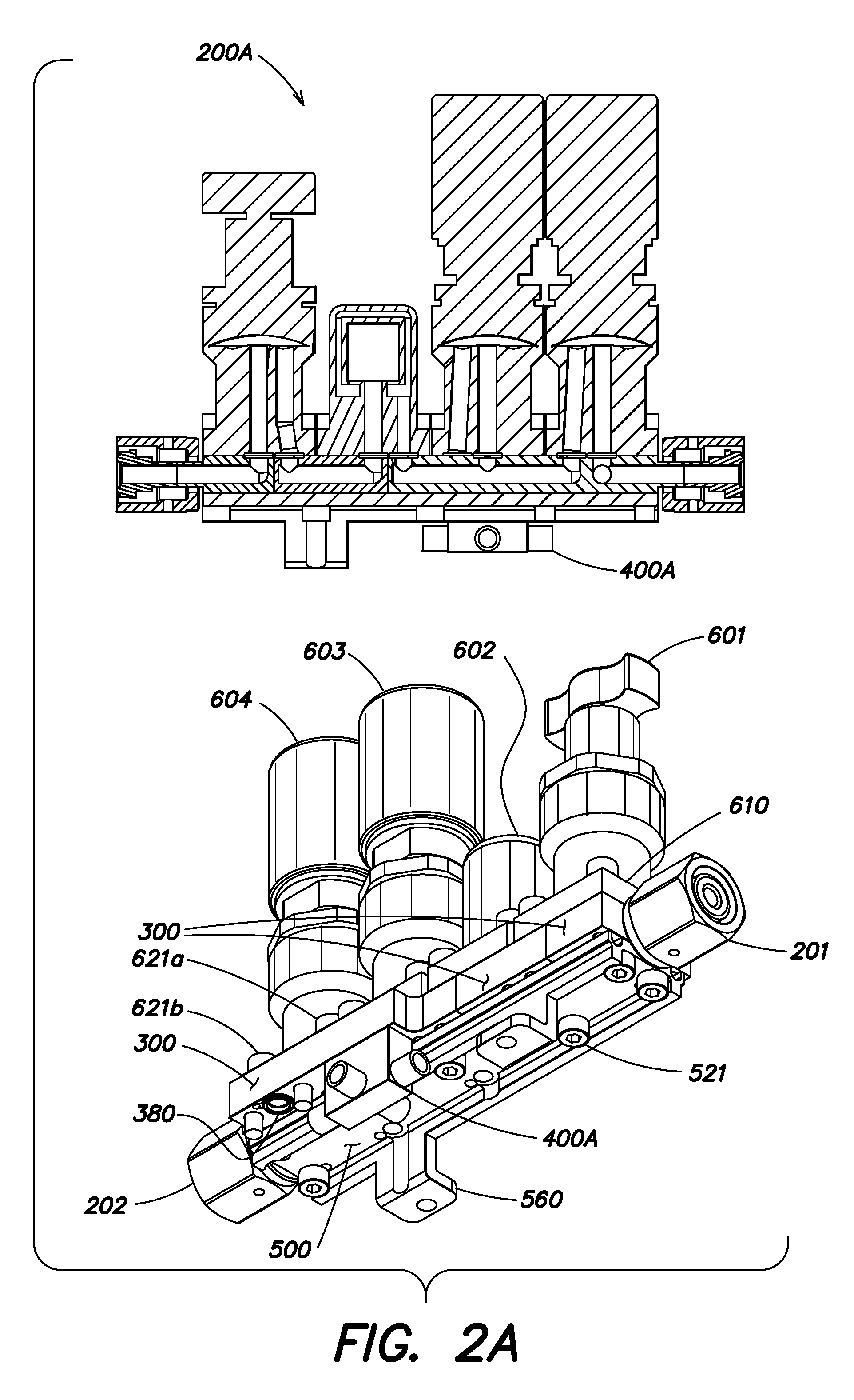
[0049]FIG. 3A illustrates a collection of modular flow substrates and modular manifolds in accordance with the present invention for use with fluid handling components having asymmetric port placement (e.g., C-seal components) in which one of the ports of the fluid handling component is axially aligned with the center of the component and the other is situated off axis. (See, for example, the cross-sectional (i.e., upper) drawing in FIG. 2A in which each of the fluid handling components 60X has such an asymmetric port placement). As details of the various modular flow substrates and modular manifolds depicted in FIG. 3A are described more fully in detail with respect to other figures below, only a general description of FIG. 3A is provided herein.

[0050]The top row of FIG. 3A illustrates plan and elevation views of various flow substrates 300A in which the component conduit ports 320a, 320b, 320c formed in the component attachment surface 305 are arranged to fluidly communicate with ...

second embodiment

[0077]Indeed, it should be appreciated that although FIGS. 9A and 9B show a number of different flow substrates 300A′ and manifolds 400A′ and 400B,′ only a limited number of the possible porting arrangements are illustrated. In this regard, it should be appreciated that the same variations in porting arrangements shown with respect to the flow substrates 300A and the manifolds 400A and 400B in FIGS. 3A and 3B may be provided with respect to the flow substrates 300A′ and the manifolds 400A′ and 400B′. Because the main distinction between the flow substrates and manifolds of this second embodiment relate primarily to the symmetric (rather than asymmetric) placement of the component conduit ports 320 and the particular manner in which the component conduit ports are adapted to receive a particular type of seal (e.g., a W-Seal™), only the differences are described in detail herein.

[0078]Depicted in FIG. 9A are two new structures 900 and 901 that are unique to this second embodiment, but...


PUM


Abstract

A fluid delivery system that includes flow substrates and manifolds that minimize the number of fluid conduit ports and seals needed to build standardized fluid delivery sticks. Each flow substrate has a component attachment surface with one or more component conduit ports and an associated plurality of fastener apertures. Some flow substrates incorporate a transverse manifold connection conduit port on a surface opposite the component attachment surface. Fastener apertures associated with the transverse manifold connection conduit port are accessible adjacent to installed fluid handling components. Transverse connection between fluid delivery sticks use a welded assembly of fluid conduits to provide a transverse connecting lower layer which is sealingly retained by fasteners inserted from above through apertures associated with the transverse manifold connection conduit port. Flow substrates for each fluid delivery stick are fastened to a standardized bracket and each fluid delivery stick arrangement can be assembled and tested as an integrated subassembly.

Description

RELATED APPLICATIONS[0001]This application claims priority under 35 U.S.C. §119(e) to U.S. Provisional Application Ser. No. 61 / 178,286, entitled “FLUID DELIVERY SUBSTRATES FOR BUILDING REMOVABLE STANDARD FLUID DELIVERY STICKS,” filed on May 14, 2009, which is herein incorporated by reference in its entirety.BACKGROUND OF THE INVENTION[0002]1. Field of the Invention[0003]The present invention is directed to fluid delivery systems, and more particularly to surface mount fluid delivery systems for use in the semiconductor processing and petrochemical industries.[0004]2. Discussion of the Related Art[0005]Fluid delivery systems are used in many modern industrial processes for conditioning and manipulating fluid flows to provide controlled admittance of desired substances into the processes. Practitioners have developed an entire class of fluid delivery systems which have fluid handling components removably attached to flow substrates containing fluid pathway conduits. The arrangement of...

Claims


Application Information

Patent Timeline
IPC IPC(8): F16K11/10
CPCF16K27/003Y10T137/87885
Inventor VU, KIM NGOC
Owner COMPART SYST PTE LTD
Why Eureka
Try Eureka