Active bolster mounting system

Inactive Publication Date: 2012-11-13
FORD GLOBAL TECH LLC
View PDF15 Cites 11 Cited by
  • Summary
  • Abstract
  • Description
  • Claims
  • Application Information

AI Technical Summary

Benefits of technology

[0007]The present invention employs a bracket for mounting a bolster directly to a trim panel so that the gap and flushness of the interface between the bolster and trim panel are well controlled. A high quality of pre-deployment appearance and deployment performance are a

Problems solved by technology

With both the bolster and trim substrate panel independently mounted to the door frame, it can be a challenge to accurately control placement of the bolster within the opening so that the gap has a constant width around the periphery and so that the A-surface flushness (i.e., matching the depth of the outer surfa

Method used


Image

  • Active bolster mounting system
  • Active bolster mounting system
  • Active bolster mounting system

Examples


Embodiment Construction

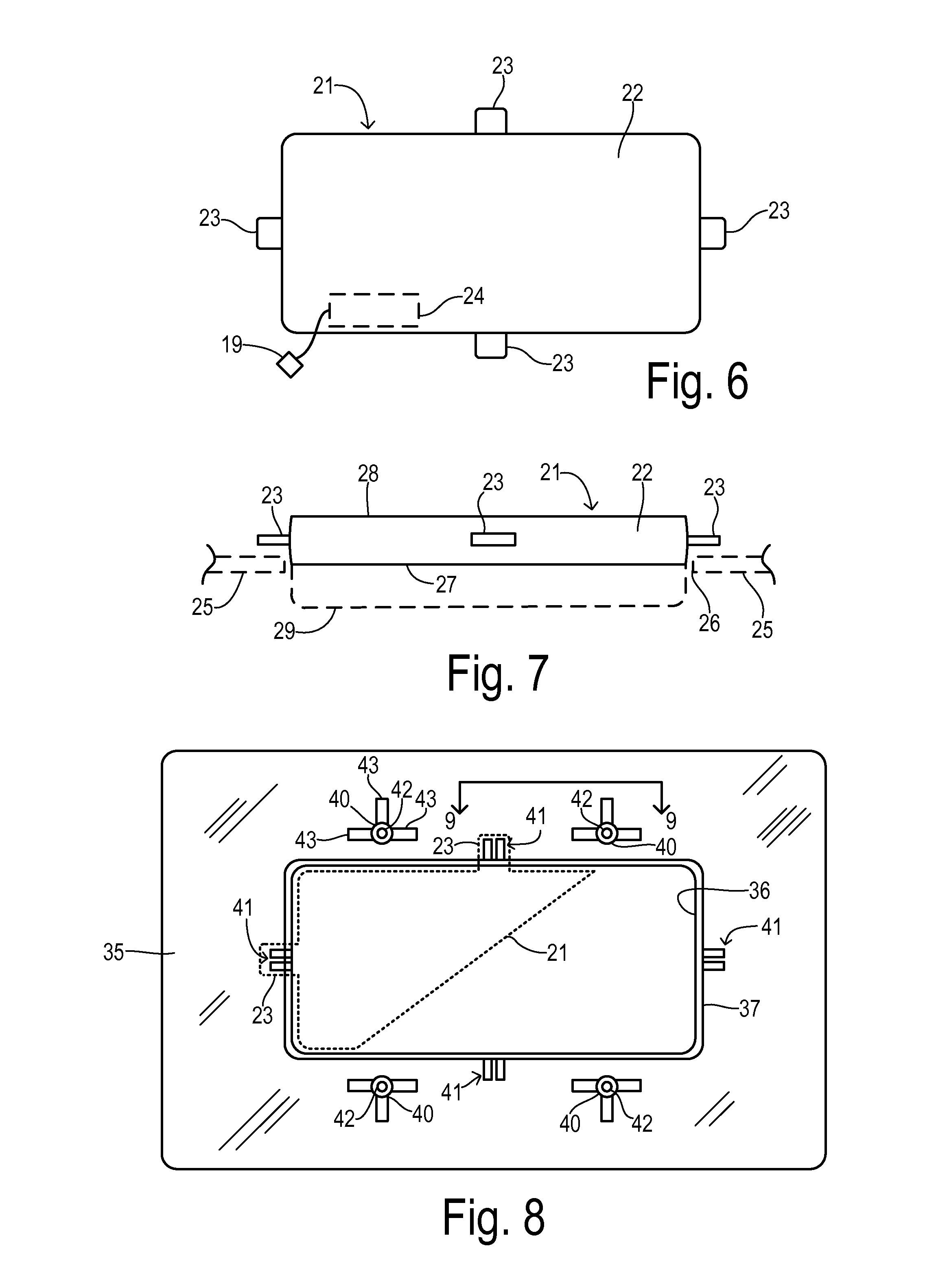
[0022]A bolster of the present invention is comprised of a hollow chamber which may be blow molded as a single unit or injection molded in separate parts that may be welded together to form a hermetically sealed chamber. One surface of the chamber provides an A-side as a continuous “Class A” passenger-facing surface of a door panel, for example. The B-side the bolster is mounted to face a structural element of a vehicle such as an internal door frame.

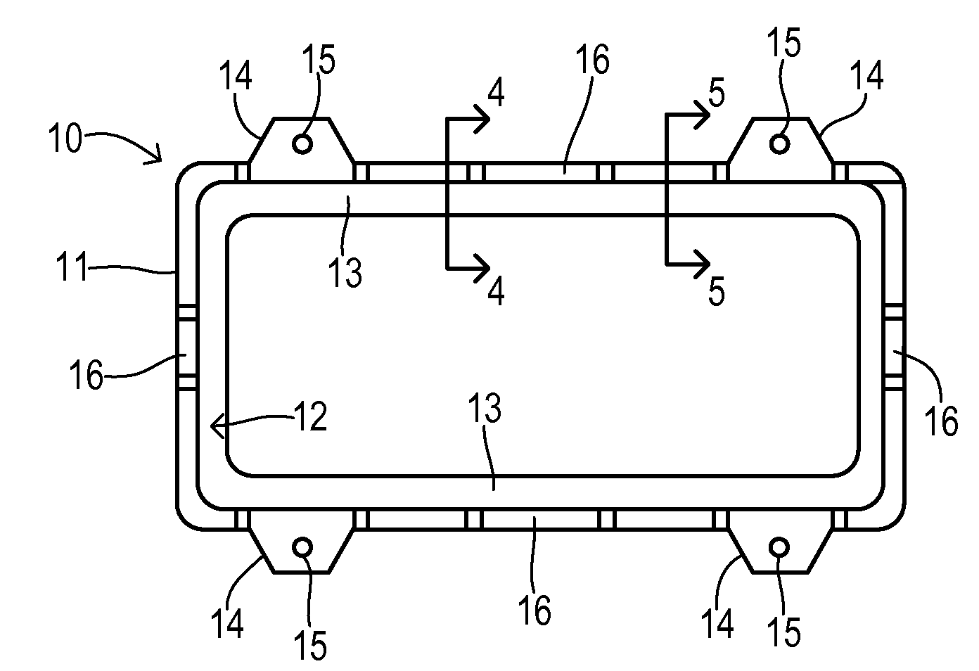
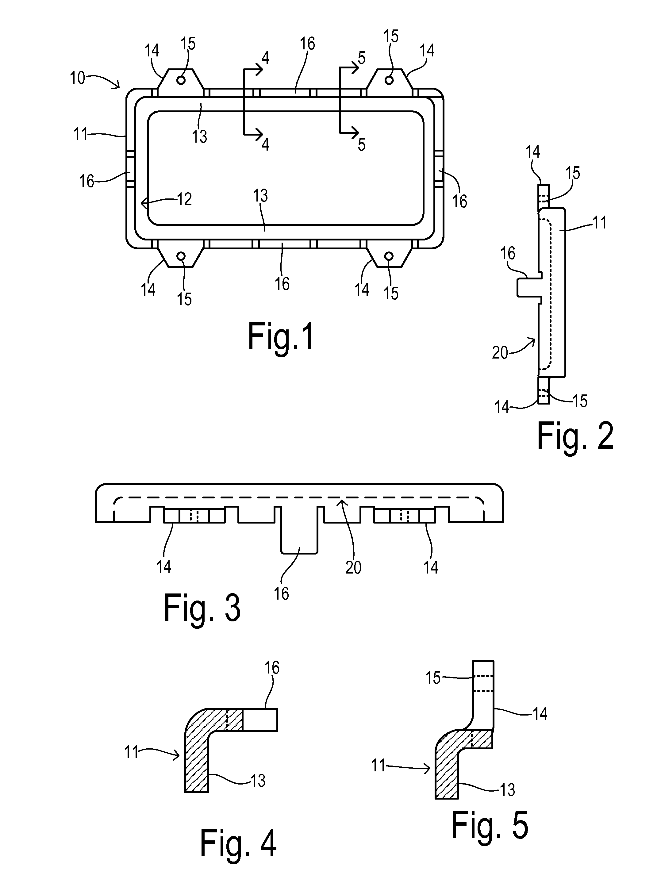
[0023]An active bolster may be attached to a trim substrate panel using a retainer bracket 10 as shown in FIG. 1. Retainer bracket 10 is shaped as a frame 11 that may be manufactured as an injection molded plastic or a stamped metal component, for example. Frame 11 has a generally L-shaped channel 12 with a reaction surface 13 for receiving a B-side of the bolster. Reaction surface 13 may extend concentrically along an inner periphery of frame 11 as shown in FIG. 1, or may alternatively be formed as a planar backing surface completely f...


PUM


Abstract

An active bolster system for a vehicle includes a trim substrate panel adapted to be mounted to a structural element of the vehicle, wherein the substrate panel has a bolster opening. A bolster has a main body configured to fit within the bolster opening, wherein the main body has an A-side substantially flush with the substrate panel and a B-side facing the structural element. The main body has a plurality of lateral side tabs extending from the main body, and the main body expands during a deployment of the active bolster system so that a distance between the A-side and B-side increases. A retainer bracket retains the bolster against the substrate panel, wherein the retainer bracket comprises a frame extending around a periphery of the main body. The frame includes a reaction surface disposed against at least a portion of the B-side, a plurality of pinch tabs each pressing a respective lateral side tab against the substrate panel, and a plurality of rigid attachments for directly attaching the is retainer bracket to the substrate panel. Reaction forces applied by the bolster against the reaction surface during at least an initial expansion of the main body during the deployment are transmitted by the retainer bracket to the substrate panel so that separation is urged between the main body and the substrate panel, and the substrate panel is urged against the structural element.

Description

CROSS REFERENCE TO RELATED APPLICATIONS[0001]Not Applicable.STATEMENT REGARDING FEDERALLY SPONSORED RESEARCH[0002]Not Applicable.BACKGROUND OF THE INVENTION[0003]The present invention relates in general to active bolsters for automotive crash protection systems, and, more specifically, to a system for retaining an active bolster within an interior trim panel.[0004]In order to reduce loads applied to an occupant from impact during a vehicle crash, active bolster systems are sometimes deployed within a vehicle interior. They may be located in an instrument panel or glove box door to protect the knees or in a door panel, window pillar, or seat structures to protect against side impacts. A typical active bolster is formed from a plastic material shaped into a bellows configuration on one surface. Upon the occurrence of a crash event of sufficient magnitude, an inflator is activated to inflate the bolster and expand the bellows to create an impact cushion.[0005]An active bolster assembly...

Claims


Application Information

Patent Timeline
IPC IPC(8): B60R21/206
CPCB60R21/04B60R2021/0407
Inventor ORLOWSKY, MICHAEL G.KALISZ, RAYMOND E.
Owner FORD GLOBAL TECH LLC
Why Eureka
Try Eureka