Optimized planer feeder system and method

a planer feeder and optimizer technology, applied in the field of optimizing the planer feeder, can solve the problems of difficulty, inability to achieve the effect of high grade and/or appearance, and maximize grade and recovery

Active Publication Date: 2007-01-30
USNRKOCKUMS CANCAR
View PDF7 Cites 12 Cited by
  • Summary
  • Abstract
  • Description
  • Claims
  • Application Information

AI Technical Summary

Benefits of technology

[0012]In these and other respects, the optimized planer feeder system and method according to the present invention substantially departs from the conventional concepts and designs of the prior art, and in so doing provides an apparatus primarily developed for the purpose of improved recovery, higher throughput, and grade uplift through automatic optimum wane orientation at the planermill.
[0017]Another object is to provide an optimized planer feeder system and method that automatically orients to maximize the wide face or narrow face or both faces of the piece and hence the highest grade and / or appearance.
[0018]Another object is to provide an optimized planer feeder system and method that includes the capability of modifying the settings within grade to achieve ideal end match conditions so the planer controls require no abrupt motions between pieces.
[0019]Another object is to provide an optimized planer feeder system and method that may be ribbon fed and does not have to make large moves between pieces.
[0020]Another object is to provide an optimized planer feeder system and method that can determine the effects on grade by other board characteristics such as knots, splits, crook, bow, strength, and adjust the orientation and or planer settings so that the wane produced is consistent with the other grade limiting characteristics.
[0021]Another object of the invention is to evaluate the piece and remove recoverable trim blocks prior to planing so that the trim blocks may be fingerjointed and then planed to size, taking advantage of the excess wood to maximize grade and recovery.

Problems solved by technology

The main problem with the conventional manual planer infeed is that the operator would have to flip 100% of the pieces to properly view all faces, and some portion of those twice if the worse face is not correct after the first flip.
Another problem with the conventional planer feeder is that when pieces press against each other, it makes flipping harder due to friction.
A further problem with the sawmill marking system is that the drying process may introduce other grade limiting characteristics which would change the decision.
An improperly oriented piece has potential for either grade or volume depreciation.
⅛ inch of length, or 0.125″=0.0003125 seconds at 400 inches / sec which is a challenge and may not be feasible.
If the mill allows an extra one inch in length then the sets must be achieved within 0.0025 seconds, which is still a challenge.

Method used


Image

  • Optimized planer feeder system and method
  • Optimized planer feeder system and method
  • Optimized planer feeder system and method

Examples


Embodiment Construction

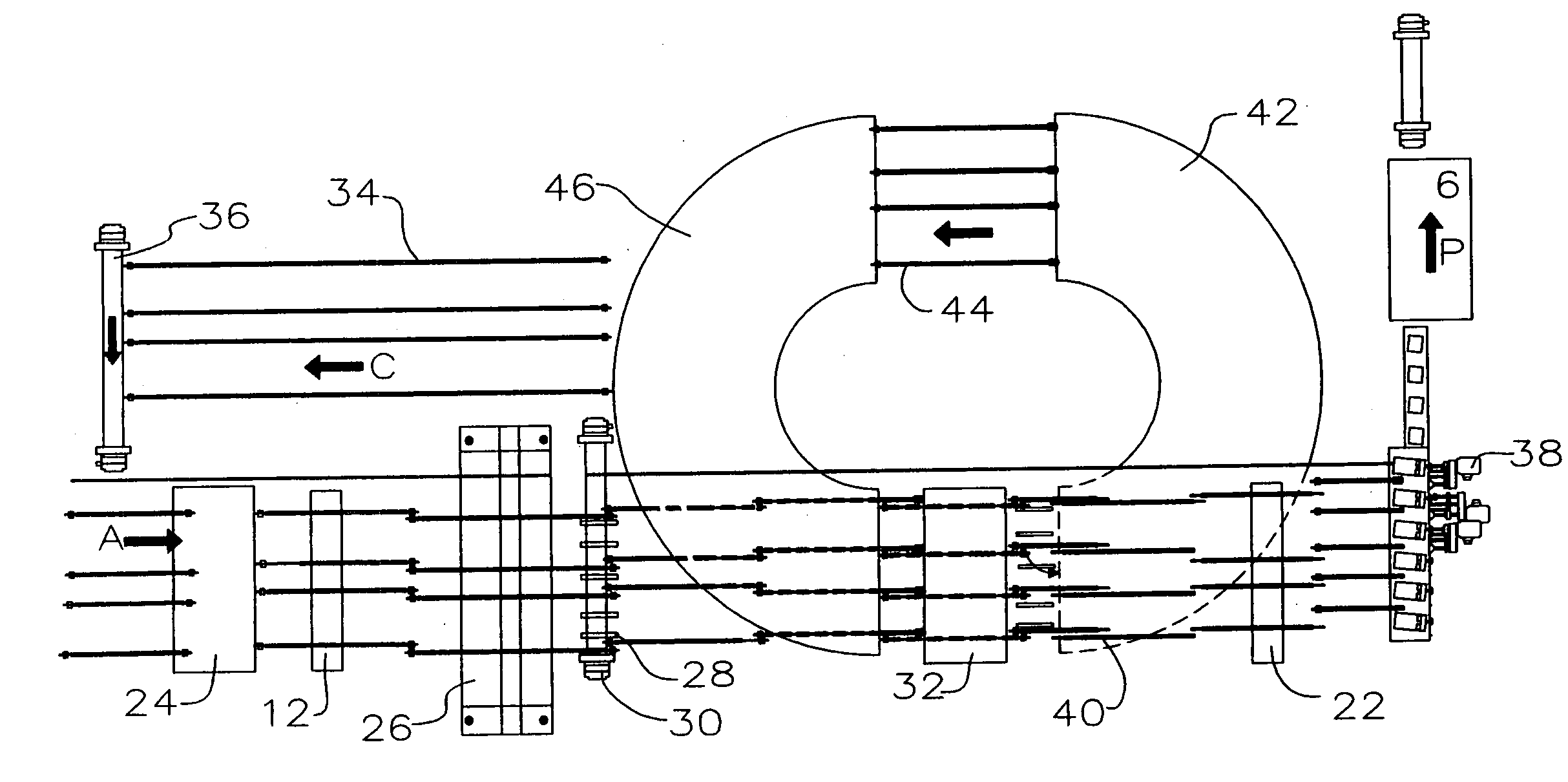
[0149]Turning now descriptively to the drawings, in which similar reference characters denote similar elements throughout the several views, the attached figures illustrate an optimized planer feeder system and method, which comprises, firstly, measurement and evaluation of a board for example after drying in the kilns, although lumber may be planed before drying, in a planer mill, and secondly, automatically orienting the board for highest value planing in the planer. The invention also provides the means to measure the board in either linear or lateral flow, determining the optimum orientation, and then to turn, flip and turn, or only flip the board as appropriate for optimization.

[0150]Upstream of the planer, a board is measured by a scanner and then evaluated by the processing logic of an optimizing processor. Advantageously, each board is scanned and individually optimized because of the fact that every board may have unique defect characteristics, the primary example of which ...


PUM


Abstract

An apparatus for optimizing orientation of a workpiece in a planermill for feeding of the workpiece into a planer includes an infeed to the planer, a workpiece turner for selectively turning the workpiece end-for-end upstream of the planer on the infeed a workpiece flipper for selectively flipping the workpiece one hundred eighty degrees about a longitudinal axis of the workpiece upstream of the planer on the infeed, a scanner on the infeed upstream of the workpiece turner and workpiece flipper for detecting defects on the workpiece, a processor cooperating with the scanner, the workpiece turner and the workpiece flipper for optimizing the orientation of the workpiece relative to status and actively translatable cutterheads in the planer.

Description

CROSS REFERENCE TO RELATED APPLICATION[0001]This application claims priority from U.S. Provisional Patent Application No. 60 / 474,953 filed Jun. 3, 2003 entitled Optimized Planer Feeder System and Method.FIELD OF THE INVENTION[0002]The present invention relates generally to a planer feeder optimizer and more specifically it relates to an optimized planer feeder system and method for improved recovery, grade uplift, and optimum wane orientation at the planermill.BACKGROUND OF THE INVENTION[0003]In the prior art, planer mills have been orienting the lumber fed into the planer to place the most wane face and / or edge to the planer cutter which removes the largest amount of material thus providing the least wane on the finished planed lumber. Planer feeder automation systems have been in use for years. Typically, planer feeder automation includes piece orientation as described in a Forintek document #680-3366 dated August 2001. The lug loader such as described in U.S. Pat. No. 4,869,360 s...

Claims


Application Information

Patent Timeline
Patent Type & Authority Patents(United States)
IPC IPC(8): G05B13/02B23Q15/00B23Q16/00B27C1/00B27C1/12B27C7/00B27G1/00
CPCB27G1/00B27C1/12
Inventor BAKER, LYLESTEVENS, RAY
Owner USNRKOCKUMS CANCAR
Why Eureka
Try Eureka