Processes and apparatuses for enhanced cutting using blends of abrasive materials

a technology of enhanced cutting and abrasive materials, applied in the field of waterjet systems, can solve the problems of high material cost, low cutting rate achieved by garnet abrasives, and unsuitable for cost-effective processing

Active Publication Date: 2012-11-13
FLOW INT CORP
View PDF16 Cites 23 Cited by
  • Summary
  • Abstract
  • Description
  • Claims
  • Application Information

AI Technical Summary

Problems solved by technology

Unfortunately, cutting rates achieved utilizing garnet abrasive may be relatively low, especially when cutting workpieces made of hard, wear-resistant materials, such as ceramics (e.g., alumina ceramic, zirconia, etc.), ceramic matrix composites, carbides (e.g., tungsten carbide, titanium carbide, and the like), sapphire, and other materials capable of withstanding exposure to abrasive jets, such as materials often used to make armor (e.g., armor for military vehicles, body armor, etc.).
Even though garnet abrasive has a low material cost, it may result in an expensive, time consuming manufacturing process, especially if used to cut these hard, wear-resistant materials, thus rendering it unsuitable for cost-effective processing.
Unfortunately, hard abrasives often have a high material cost and produce high wear rates of the mixing tube that result in frequent mixing tube replacement.
When an abrasive jet carrying only hard abrasive passes through the mixing tube at a high velocity, the mixing tube, even if made of a wear-resistant material, experiences appreciable wear.
Frequent replacement of worn mixing tubes often leads to problems, such as damage to the cutting head body, misalignment of the mixing tube, machine downtime, and the like.
Accordingly, hard abrasive is unsuitable for cost-effective processing.
Also, increasing the working pressure of the fluid used to make the abrasive jet may not significantly increase cutting rates of many types of hard materials.

Method used


Image

  • Processes and apparatuses for enhanced cutting using blends of abrasive materials
  • Processes and apparatuses for enhanced cutting using blends of abrasive materials
  • Processes and apparatuses for enhanced cutting using blends of abrasive materials

Examples


Embodiment Construction

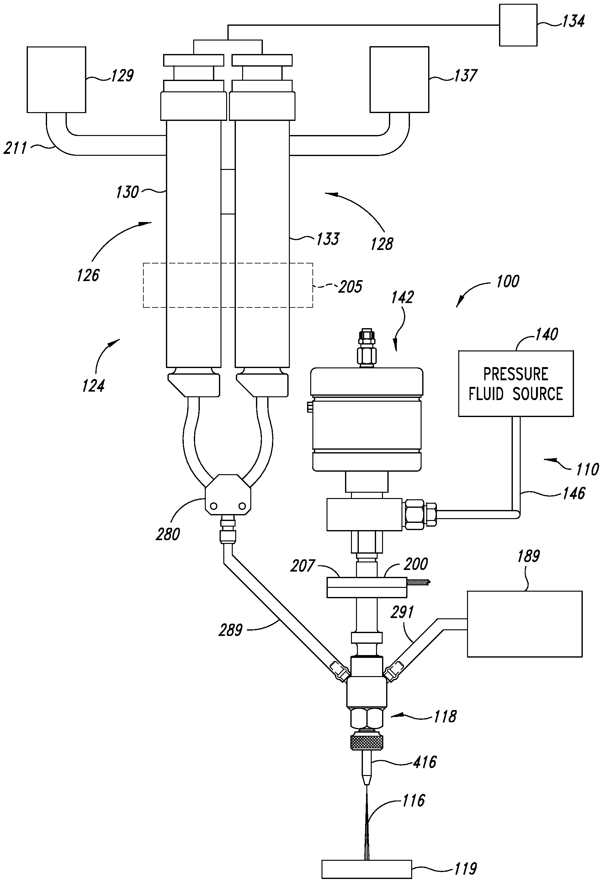
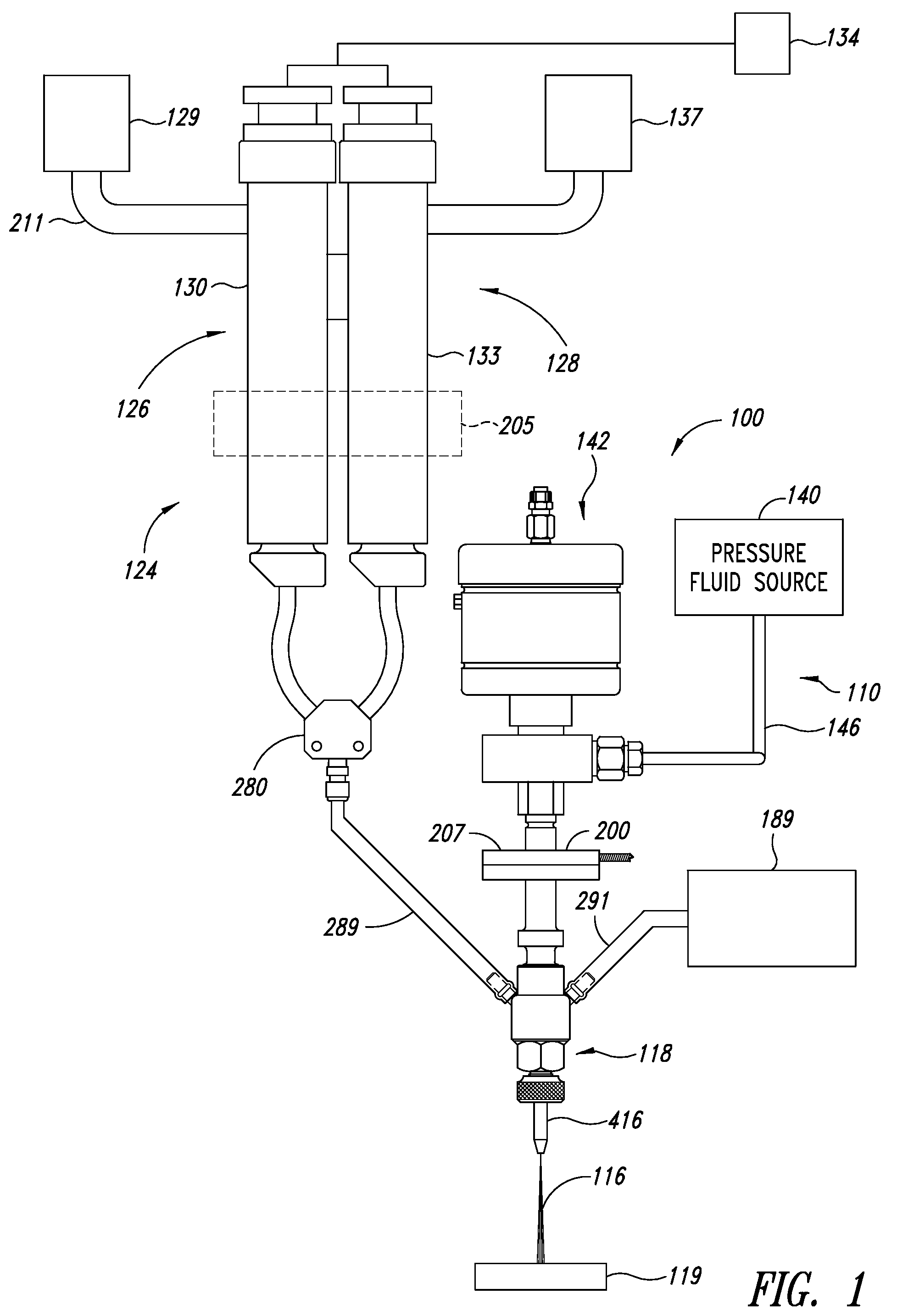
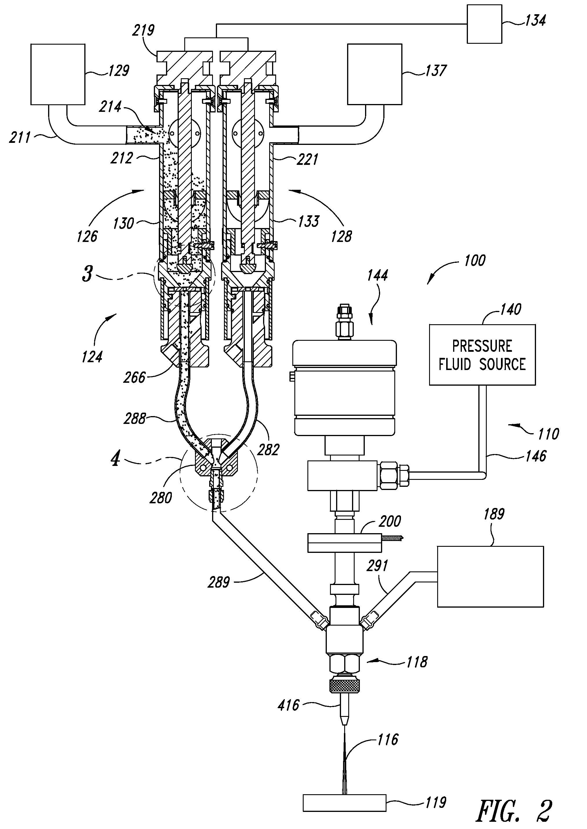
[0026]FIG. 1 shows a waterjet system 100 producing a jet 116 that is processing a workpiece 119. The waterjet system 100 generally includes a cutting head assembly 118, a fluid delivery system 110 for delivering pressurized fluid to the cutting head assembly 118, and an abrasive delivery system 124 for delivering abrasive to the cutting head assembly 118. The abrasive delivery system 124 generally includes a first abrasive feed apparatus 126, a second abrasive feed apparatus 128, and a mixing manifold 280 between the first and second feed apparatuses 126, 128 and the cutting head assembly 118.

[0027]To produce a fluid jet, the abrasive delivery system 124 can be OFF while the fluid delivery system 110 delivers pressurized fluid (e.g., water) to the cutting head assembly 118. The cutting head assembly 118 uses the pressurized fluid to produce the fluid jet 116. To produce an abrasive jet, the abrasive delivery system 124 is turned ON and delivers abrasive to the cutting head assembly ...


PUM

PropertyMeasurementUnit
pressuresaaaaaaaaaa
pressureaaaaaaaaaa
pressureaaaaaaaaaa

Abstract

A waterjet system selectively produces fluid jets for water jet cutting or abrasive jets for abrasive-waterjet-cutting. The abrasive materials in the abrasive jet are determined based on the properties of the workpiece. The waterjet system includes an abrasive delivery system that is capable of delivering either a single abrasive or a plurality of abrasives as an abrasive blend, to a cutting head assembly. The cutting head assembly entrains the abrasive into a fluid jet to form an abrasive jet.

Description

BACKGROUND[0001]1. Technical Field[0002]The present invention relates generally to waterjet systems and, in particular, to abrasive jet systems capable of producing multi-abrasive jets.[0003]2. Description of the Related Art[0004]Conventional waterjet systems are used to process workpieces by pressurizing fluid and then delivering the pressurized fluid against a workpiece. An abrasive jet system is a type of waterjet system that produces a high-pressure abrasive jet suitable for cutting through relatively hard materials. Abrasive jet systems often have a jewel orifice in a cutting head assembly. High-pressure fluid flows through the jewel orifice to form a high-pressure fluid jet inside of the cutting head assembly. Abrasive is entrained in the fluid jet to produce an abrasive jet. The abrasive jet passes through a mixing tube retained by a cutting head body and is ultimately discharged towards the workpiece.[0005]Garnet abrasive is commonly used to produce abrasive jets suitable fo...

Claims


Application Information

Patent Timeline
Patent Type & Authority Patents(United States)
IPC IPC(8): B24B49/00
CPCB24C5/02Y10T83/0591Y10T83/364
Inventor HASHISH, MOHAMEDCRAIGEN, STEVEN J.
Owner FLOW INT CORP
Why Eureka
Try Eureka