Process for preparing of a catalyst solution for fuel cell and a membrane electrode assembly using the same

a technology of membrane electrodes and catalyst solutions, which is applied in the direction of fuel cells, cell components, electrical equipment, etc., can solve the problems of difficult to apply a small amount of ink, difficult to obtain homogeneous catalyst layers, and difficult to substantially develop electrochemical performan

Inactive Publication Date: 2012-11-13
HANWHA CHEMICAL CORPORATION
View PDF19 Cites 0 Cited by
  • Summary
  • Abstract
  • Description
  • Claims
  • Application Information

AI Technical Summary

Benefits of technology

[0014]The object of the present invention is to provide a catalyst solution for a membrane-electrode assembly in a fuel cell, and a process for preparing the membrane-electrode assembly using the same, wherein the process yield can be enhanced as compared to conventional techniques, the electrochemical performance is excellent, and the amount of application of the catalyst particles can be easily controlled, in order to overcome the problems of conventional techniques as mentioned above.Technical Solution
[0020]Then the ion conductive resin solution (Solution B) prepared by dissolving the ion conductive resin in water, low boiling point solvent or aqueous solution of low boiling solvent, is added to the catalyst solution (Solution A), and dispersed by using a homogenizer or a bead mill to obtain the mean size (d50) of the catalyst particles of 2 μm or less. The ion conductive resin partly serves to prevent cohesion of particles by being adsorbed on the surface of catalyst particles to induce electric repulsion or steric repulsion between the particles.
[0028]The pH modifier serves to control zeta potential of the ink to increase dispersion stability. Conventional acidic or basic organic substances can be used.
[0029]The leveling agent levels the surface of the catalyst layer after application, to prevent mechanical damage of interface when preparing the membrane-electrode assembly in combination with the gas diffusion electrode upon application. Conventional surfactants may be used, but fluorine-containing surfactants are most suitable. According to the present invention, the amount of functional additives as described above preferably is not more than 1% by weight with respect to the catalyst solution prepared according to the invention.
[0032]According to the process of the present invention, catalytic solution for a fuel cell can be prepared, with increased process yield and excellent electrochemical performance as compared to the process by conventional techniques, and the amount of the catalyst particles to be coated can be easily controlled.
[0035]The present invention is advantageous in that the porous structure of the membrane-electrode catalyst layer is controlled as 3-dimensional network structure by adjusting the size of particles dispersed in the catalyst solution, the viscosity, and surface tension of the solvent.

Problems solved by technology

According to the latter process, catalyst particles are apt to be depressed in the porous gas diffusion electrode, so that a homogeneous catalyst layer can be hardly obtained.
In addition, mechanical damage may occur due to compression, and the pore structure cannot be appropriately controlled in the coated catalyst layer, so that electrochemical performance cannot be substantially developed.
In case of employing screen printing or roller printing, it is difficult to apply a small amount of ink, while the polymer electrolyte membrane is apt to expand with an increased amount of coated ink, on the other hand.
In case of ink-jet printing, the disadvantage indicated is that the coating time is too long to reduce the productivity since the amount of ink to be coated is substantially a trace amount.
However, problems have been indicated in that, clogging of the spray nozzle may occur when the solvent is evaporated or dispersion stability of catalyst particles is lowered at the time of coating on the electrolyte membrane, thereby causing reduced process yield and difficulties in controlling the amount of coating.
However, those techniques were unsatisfactory to fulfill the purposes of compatibility of gas diffusion property, ion conductivity and moisturizing property, and they might cause environmental problems due to use of excessive amount of organic solvent.

Method used


Image

  • Process for preparing of a catalyst solution for fuel cell and a membrane electrode assembly using the same
  • Process for preparing of a catalyst solution for fuel cell and a membrane electrode assembly using the same
  • Process for preparing of a catalyst solution for fuel cell and a membrane electrode assembly using the same

Examples


example 1

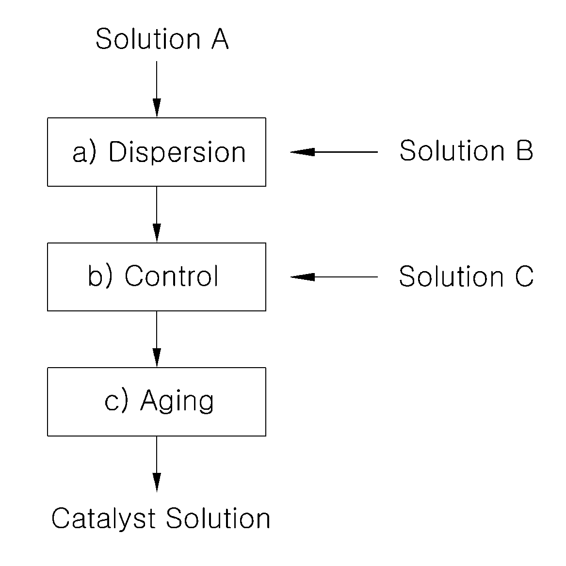
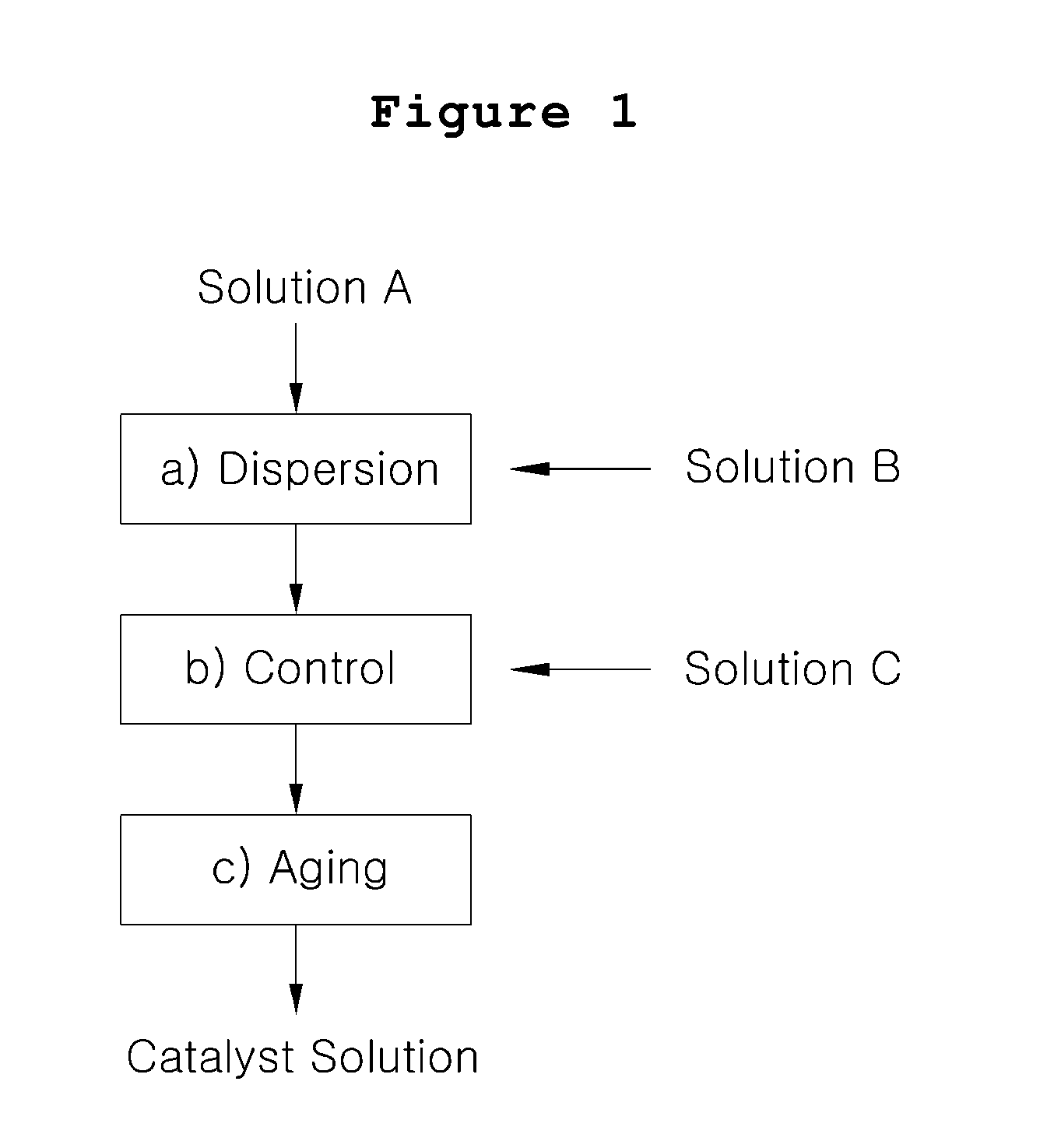
[0042]Platinum catalyst carried on carbon particles (TEC10V50E, manufactured by Tanaka Kabushiki Kaisha, 50% by weight Pt / C) (5.3 g) was mixed with water (25 g), and the mixture was stirred in an agitation barrel to prepare Solution A.

[0043]Separately, isopropyl alcohol (21 g) as low boiling point solvent was mixed with ion conductive resin solution containing 5% by weight of Nafion (Nafion solution DE512 manufactured by Du Pont) (31.6 g), and the mixture was stirred to prepare Solution B.

[0044]Solution B was incorporated to Solution A under stirring, and the mixture was dispersed by using an airtight homogenizer for 1 hour. Then, Solution C comprising water (6.6 g) and ethylene glycol (10.6 g) as high boiling point solvent mixed therein was added thereto. The resultant mixture was stirred for 10 hours to prepare catalyst slurry.

[0045]The catalyst slurry thus prepared was aged at the temperature lower than 5° C. for 24 hours, and coarse particles were removed by using a polymer memb...


PUM

PropertyMeasurementUnit
temperatureaaaaaaaaaa
mediate sizeaaaaaaaaaa
particle sizeaaaaaaaaaa

Abstract

The present invention discloses a process for preparing catalyst solution for a membrane-electrode assembly in a fuel cell, which comprises the steps of a) mixing a catalyst solution (Solution A) wherein catalyst particles are dispersed in water and an ion conductive resin solution (Solution B) wherein an ion conductive resin is dissolved in water, low boiling point organic solvent or a mixture thereof, to form a dispersion; b) mixing the dispersion obtained from step a) with functional additive dissolved in high boiling point solvent or a mixture of low boiling point solvent arid water (Solution C) to prepare catalyst ink dispersion; and c) aging the catalyst ink dispersion obtained from step b).

Description

TECHNICAL FIELD[0001]The present invention relates to a catalyst solution for a membrane-electrode assembly in a fuel cell, and a process for preparing the membrane-electrode assembly using the same, wherein the process yield can be enhanced as compared to conventional techniques, the electrochemical performance is excellent, and the amount of the catalyst particles to be coated can be easily controlled.BACKGROUND ART[0002]A fuel cell is a device for directly converting chemical energy of fuel into electric energy by electrochemical reaction of fuel such as hydrogen or methanol with oxygen. Differently from conventional thermal power generation, a fuel cell exhibits higher efficiency of power generation because it does not undergo Carnot cycle, with less amount of exhaust gas comprising pollutant such as NOx and SOx, without noise during operation. Thus, a fuel cell comes into the spotlight as a clear energy source for next generation.[0003]Fuel cells are classified into polymer ele...

Claims


Application Information

Patent Timeline
Patent Type & Authority Patents(United States)
IPC IPC(8): H01M4/88
CPCH01M4/881H01M4/8832H01M4/8882H01M4/8896H01M4/926H01M4/8663Y02E60/522Y02E60/50H01M4/86H01M4/88
Inventor JANG, BYUNGCHULKIM, YOUNG TAEKYANG, JUNG-EUNJIONG, YOUNGSURYU, DONG HWANSEO, MIN-HO
Owner HANWHA CHEMICAL CORPORATION
Why Eureka
Try Eureka