Method and system for providing separate write and optical modules in an energy assisted magnetic recording disk drive

a technology of energy-assisted magnetic recording and optical modules, which is applied in the direction of recording information storage, perpendicular magnetisation head, instruments, etc., can solve the problems of inadvertent overwrite, and inability to achieve the desired

Active Publication Date: 2012-11-13
WESTERN DIGITAL TECH INC
View PDF45 Cites 163 Cited by
  • Summary
  • Abstract
  • Description
  • Claims
  • Application Information

AI Technical Summary

Problems solved by technology

As a result, fabrication of magnetic and optical portions of the conventional transducer 10 may become increasingly complicated.
Such complexity in processing is generally undesirable.
Such inadvertent overwrites are generally undesirable.

Method used


Image

  • Method and system for providing separate write and optical modules in an energy assisted magnetic recording disk drive
  • Method and system for providing separate write and optical modules in an energy assisted magnetic recording disk drive
  • Method and system for providing separate write and optical modules in an energy assisted magnetic recording disk drive

Examples


Embodiment Construction

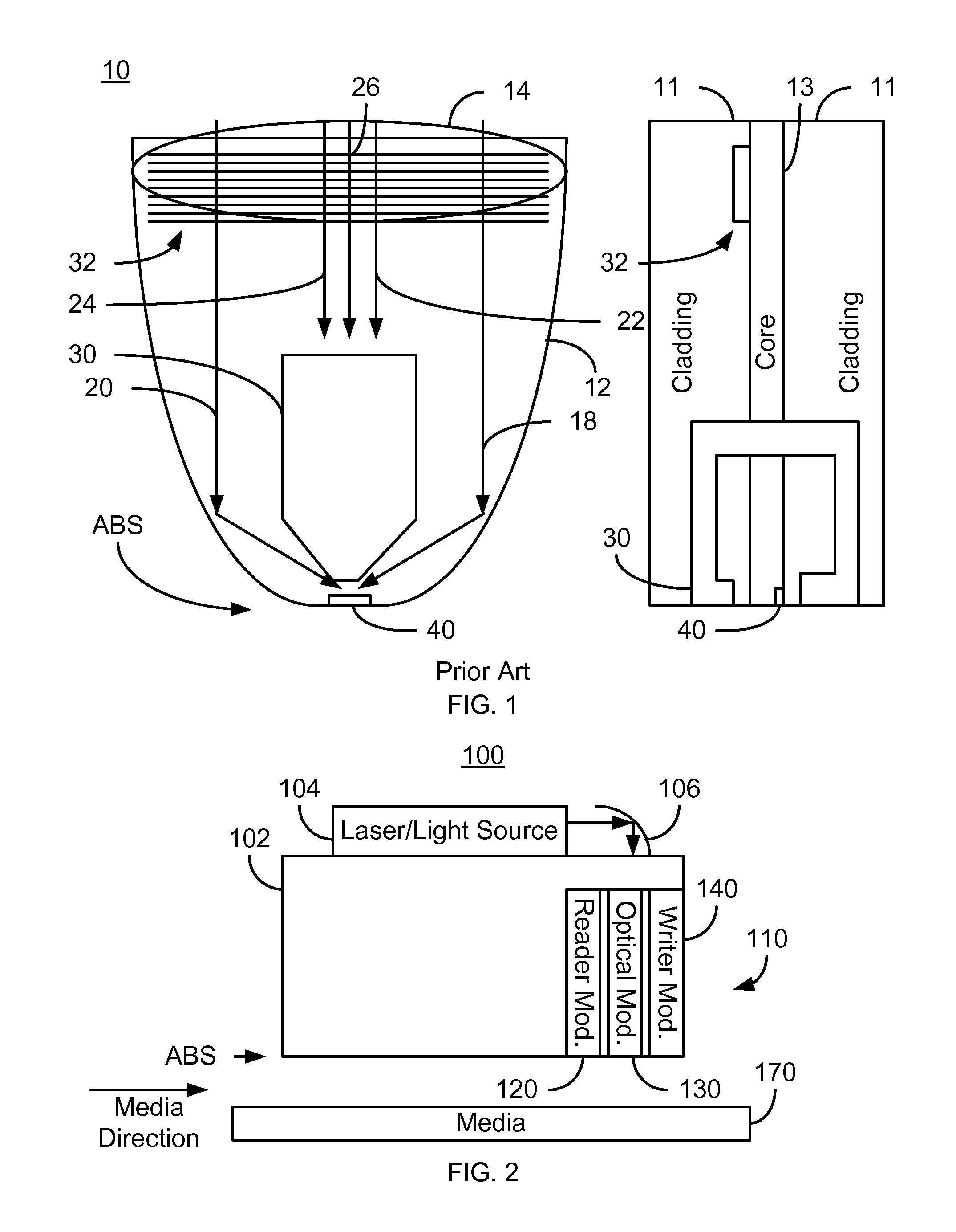
[0013]FIG. 2 is a diagram depicting a portion of an EAMR disk drive 100. For clarity, FIG. 2 is not to scale. For simplicity not all portions of the EAMR disk drive 100 are shown. In addition, although the disk drive 100 is depicted in the context of particular components other and / or different components may be used. Further, the arrangement of components may vary in different embodiments. The EAMR disk drive 100 includes a slider 102, a laser / light source 104, a mirror or other optics 106 for redirecting light from the laser 104, an EAMR head 110, and media 170. In some embodiments, the laser 104 is a laser diode. Although shown as mounted on the slider 102, the laser 104 may be coupled with the slider 102 in another fashion. For example, the laser 104 might be mounted on a suspension (not shown in FIG. 2) to which the slider 102 is also attached. The media 170 may include multiple layers, which are not shown in FIG. 2 for simplicity. For example, the media 170 may include a magne...


PUM

PropertyMeasurementUnit
angleaaaaaaaaaa
angleaaaaaaaaaa
angleaaaaaaaaaa

Abstract

An energy assisted magnetic recording (EAMR) transducer coupled with a laser is described. The EAMR transducer has an air-bearing surface (ABS) residing near a media during use. The EAMR transducer includes optical and writer modules. The optical module includes a waveguide and a near field transducer (NFT). The waveguide directs the energy from the laser toward the ABS. The NFT focuses the energy onto the media. The optical and writer modules are physically separate such that no portion of the waveguide is interleaved with a magnetic portion of the writer module. The writer module includes a write pole and coil(s). The write pole includes a pole-tip portion for providing a magnetic field to the media and a yoke. The pole-tip portion has an ABS-facing surface, a sloped surface, and a NFT-facing surface therebetween. The sloped surface is at least twenty-five and not more than sixty-five degrees from the NFT-facing surface.

Description

BACKGROUND[0001]FIG. 1 depicts top and side views of a portion of a conventional energy assisted magnetic recording (EAMR) transducer 10. For clarity, FIG. 1 is not to scale. The conventional EAMR transducer 10 is used in writing a recording media (not shown in FIG. 1) and receives light, or energy, from a conventional laser (not shown in FIG. 1). The conventional EAMR transducer 10 includes grating 32, a conventional waveguide 12 including a core 13 and cladding 11, conventional pole 30, and near-field transducer (NFT) 40. The conventional EAMR transducer 10 is shown with a laser spot 14 that is guided by the conventional waveguide 12 to the NFT 40 near the air-bearing surface (ABS). The NFT 40 focuses the light to magnetic recording media (not shown), such as a disk. Other components that may be part of the conventional EAMR transducer 10 are not shown.[0002]In operation, light from the spot 14 is coupled to the conventional EAMR transducer 10 using the grating 32. The waveguide 1...

Claims


Application Information

Patent Timeline
Patent Type & Authority Patents(United States)
IPC IPC(8): G11B11/00
CPCG11B5/1278G11B5/3116G11B5/314G11B5/6088G11B2005/0021
Inventor BATRA, SHARATTORABI, ADAM F.GIBBONS, MATTHEW R.WANG, YUGANGSTOEV, KROUM S.
Owner WESTERN DIGITAL TECH INC
Why Eureka
Try Eureka