
Control device for legged mobile robot

a mobile robot and control device technology, applied in the direction of electric programme control, program control, instruments, etc., can solve the problems of undesirable occurrence of difficulty in achieving continuous motion of the robot, and achieve the effect of reducing the deviation of the actual postur

Active Publication Date: 2012-11-13
HONDA MOTOR CO LTD
View PDF17 Cites 11 Cited by
  • Summary
  • Abstract
  • Description
  • Claims
  • Application Information

AI Technical Summary

Benefits of technology

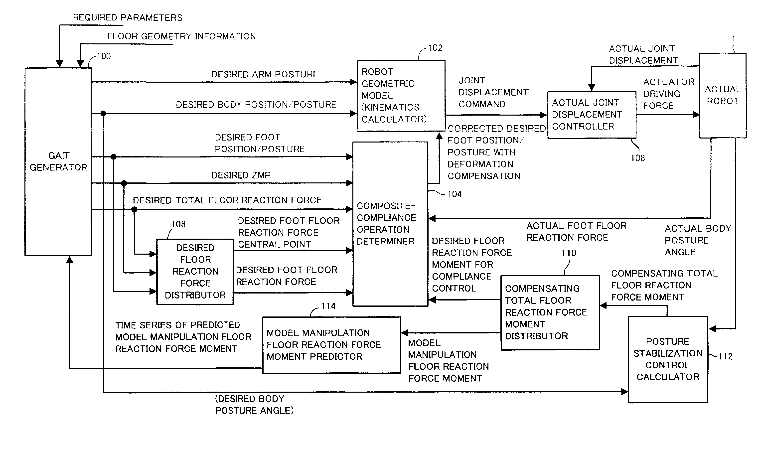
The present invention provides a control device for a legged mobile robot that can control its motion and reduce the deviation of its posture from a desired posture. The control device includes a desired motion determining unit that uses a dynamic model to calculate the necessary motion to achieve the desired posture. A motion control unit then carries out the desired motion, while a feedback manipulated variable determining unit observes the deviation of the robot's posture from the desired posture and determines an additional external force to bring it close to the desired posture. A future target determining unit predicts the future movement of the robot and a model external force manipulated variable is determined to achieve the future target. The control device can thus control the robot's motion and reduce the deviation of its posture from the desired posture.

Problems solved by technology

As a result, a motion of a desired gait that makes it difficult for the robot 1 to accomplish a continuous motion may be undesirably generated.

Method used


Image

  • Control device for legged mobile robot
  • Control device for legged mobile robot
  • Control device for legged mobile robot

Examples


Embodiment Construction

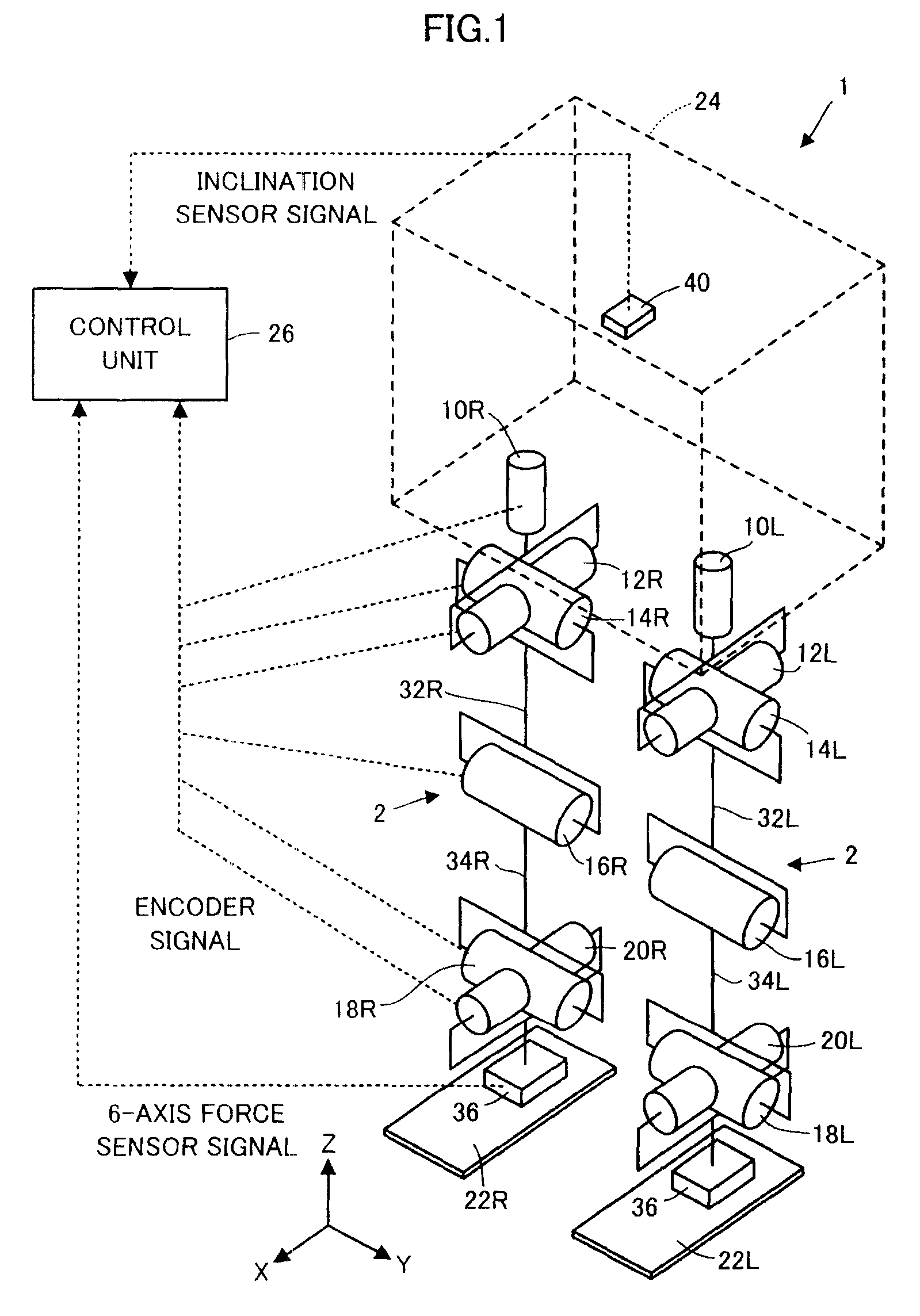
[0068]The following will describe an embodiment of the present invention by taking a bipedal mobile robot as an example of a legged mobile robot.

[0069]As illustrated in FIG. 1, a bipedal mobile robot 1 (hereinafter referred to simply as the robot 1 according to the present embodiment has a body 24 as a base body and a pair of right and left legs (leg links) 2, 2 extended from the body 24 as a moving mechanism for moving the body 24 above a floor surface.

[0070]The body 24 is connected to the proximal end portions (upper end portions) of the two legs 2, 2 through the intermediary of a waist joint (hip joint), which will be discussed later, and is supported above the floor surface by one or both of the legs 2, 2 that are in contact with the ground.

[0071]The two legs 2, 2 share the same construction and each thereof has six joints. The six joints are a joint 10R or 10L for turning a waist (hip) (for the rotation in the yaw direction relative to the body 24), a joint 12R or 12L for turni...


PUM


Abstract

A control device for a legged mobile robot has a unit which generates the time series of a future predicted value of a model external force manipulated variable as a feedback manipulated variable for reducing the deviation of the posture of the robot. A desired motion determining unit sequentially determines the instantaneous value of a desired motion such that the motion of the robot will reach or converge to a reaching target in the future in the case where it is assumed that the time series of an additional external force defined by the time series of a future predicted value of the model external force manipulated variable is additionally applied to the robot on a dynamic model.

Description

BACKGROUND OF THE INVENTION[0001]1. Field of the Invention[0002]The present invention relates to a control device for a legged mobile robot, such as a bipedal robot.[0003]2. Description of the Related Art[0004]As a technique for enhancing the stability of the posture of a legged mobile robot, which travels by moving a plurality of legs extended from a base body, the technique disclosed in, for example, Japanese Patent No. 3269852 has been proposed by the applicant of the present application.[0005]According to the technique, a state amount deviation of an actual posture of the body of a robot from a desired posture is observed, and an operational moment (an operational moment about a desired ZMP) to be additionally applied to the robot is calculated according to a PD law (proportional-differential law) from the observed value of the state amount deviation as the feedback manipulated variable (control input) required to converge the state amount deviation to zero.[0006]Further, the op...

Claims


Application Information

Patent Timeline
Patent Type & Authority Patents(United States)
IPC IPC(8): G05B19/00
CPCB62D57/032
Inventor YOSHIIKE, TAKAHIDEKANEKO, HIROYUKIORITA, ATSUO
Owner HONDA MOTOR CO LTD
Learn More