
Rotary-linear actuator with optimised rollers

a technology of optimised rollers and actuators, which is applied in the direction of gearing, mechanical equipment, hoisting equipment, etc., can solve the problems of limiting the actuator is subject to weight and space constraints, etc., and achieves the effect of increasing the useful and effective length of the threading

Inactive Publication Date: 2012-11-20
SAFRAN ELECTRONICS & DEFENSE
View PDF22 Cites 5 Cited by
  • Summary
  • Abstract
  • Description
  • Claims
  • Application Information

AI Technical Summary

Benefits of technology

[0016]Firstly, for the same longitudinal dimensions of the rollers, the invention provides a significant increase in the useful and effective length of the threading on the central part of these rollers, by an order of 20%.

Problems solved by technology

For some applications, in aerospace for example, such actuators are subject to weight and space constraints as well as constraints related to maintenance.
However, the teeth of the pinions end on the threading and their grip on the threading limits the useful and effective length of this threading.

Method used


Image

  • Rotary-linear actuator with optimised rollers
  • Rotary-linear actuator with optimised rollers
  • Rotary-linear actuator with optimised rollers

Examples


Embodiment Construction

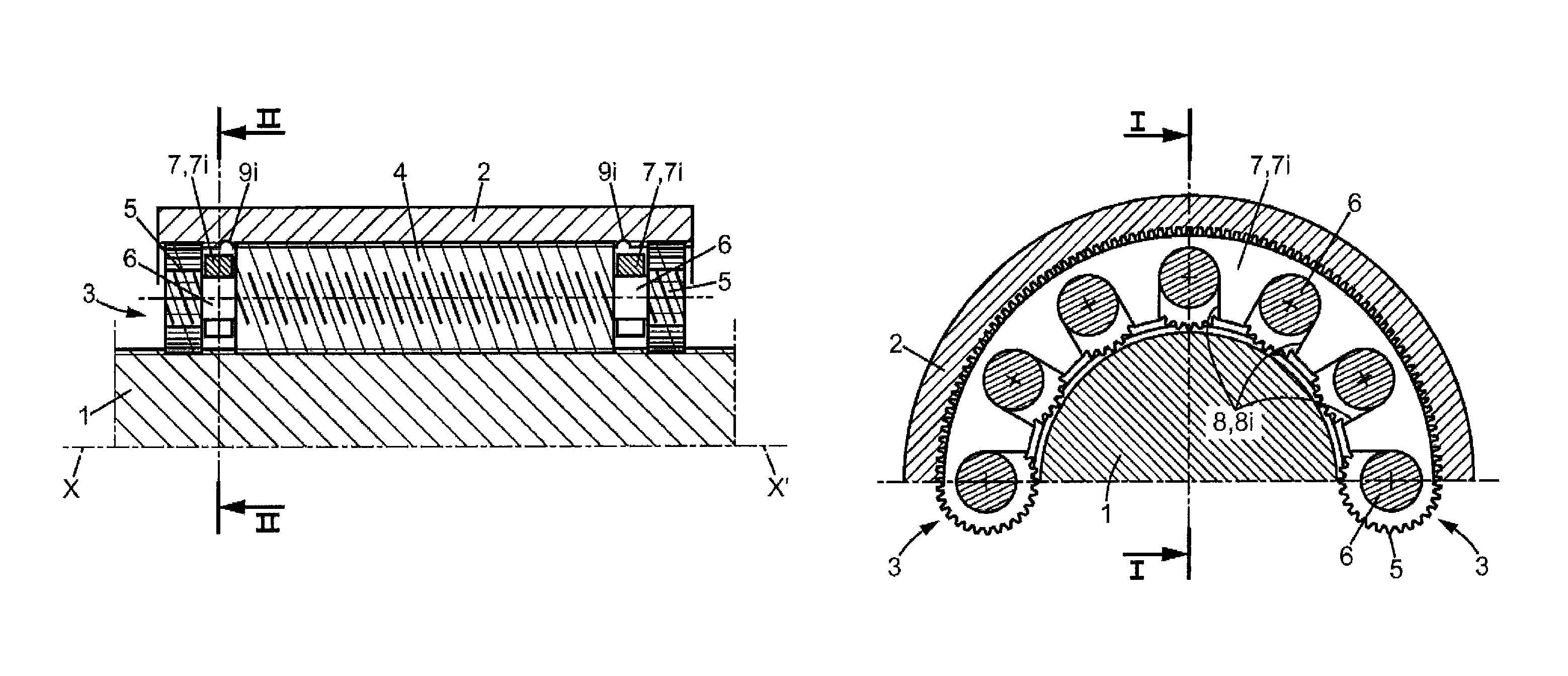
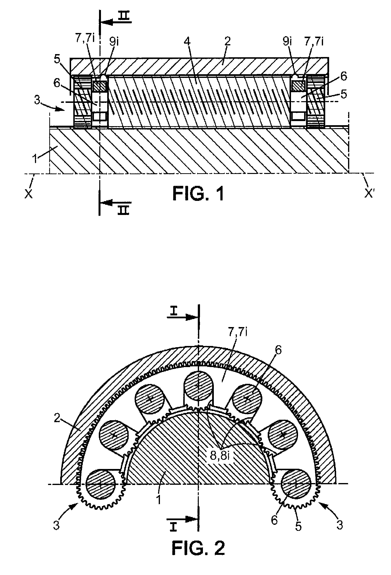
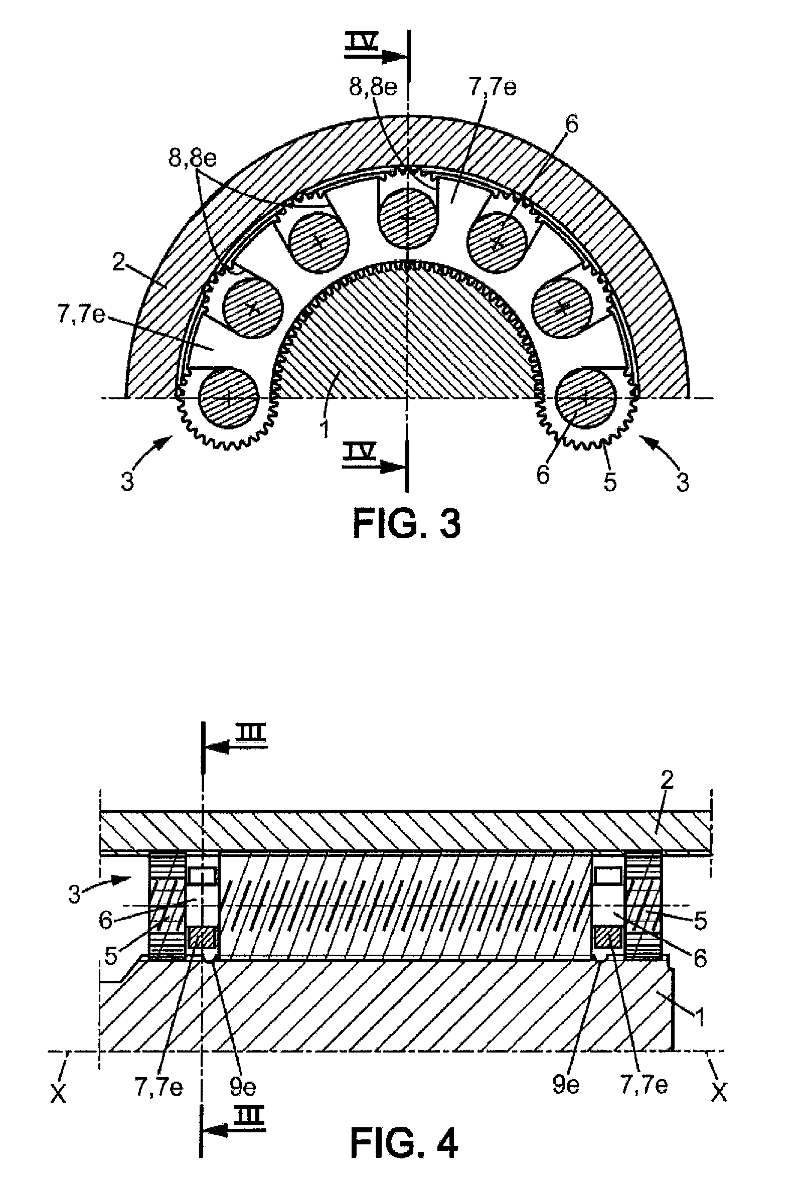
[0028]FIG. 1 shows a portion of the male part 1 and a female part 2 in the form of a sleeve which serves as a nut, with a roller 3 between the two. The two parts 1 and 2 are concentric and the roller 3 is in the form of a cylinder having an axis parallel to and offset from the axis X-X′ of said parts 1 and 2.

[0029]The roller 3 is a single unit and comprises:[0030]a central cylindrical part 4 which is threaded and which cooperates with the threading of the male part 1 and of the female part 2,[0031]a pinion 5 at each end, said pinions 5 each engaging with a set of teeth at the edge of the female part 2, and each also additionally comprising a threading which cooperates with that of the male part 1, the same threading as that of said central part 4,[0032]necks which are arranged between each pinion 5 and the central part 4, said necks being in the form of journals 6 which cooperate with the rings 7 which space the rollers 3 apart.

[0033]In this configuration illustrated in FIGS. 1 and ...


PUM


Abstract

According to the invention, an actuator device comprises rollers positioned and guided by spacer rings, and an assembly consisting of said rollers and said rings is provided between a male part and a female part. The rollers include synchronization pinions arranged at the ends thereof and include, on the threaded portion located between said pinions, annular grooves used as a journal for interfacing with open bearings in the form of notches provided on each spacer ring.

Description

CROSS-REFERENCE TO RELATED APPLICATIONS[0001]This application is a U.S. national stage filing of International Patent Application No. PCT / FR2010 / 050190 filed on Feb. 5, 2010, which claims priority under the Paris Convention to French Patent Application No. 09 50795, filed on Feb. 9, 2009.FIELD OF THE DISCLOSURE[0002]The invention relates to an improvement to current actuator devices generally referred to as rotary-linear actuators with satellite rollers.BACKGROUND OF THE DISCLOSURE[0003]These actuator devices consist of a male part and a female part which are coaxial and threaded, with satellite rollers between them, also threaded, joined by rings to form a kind of cylinder.[0004]In one case, the cylinder is integrally attached to the male part in the sense that it only rotates around this male part with no axial displacement; the threading of this male part and the threading of the rollers are inverted, with the same pitch. The female part is in the form of an internally threaded s...

Claims


Application Information

Patent Timeline
Patent Type & Authority Patents(United States)
IPC IPC(8): F16C19/50F16H55/02
CPCF16H25/2252Y10T74/19693Y10T74/18576
Inventor BONNY, FRANCK
Owner SAFRAN ELECTRONICS & DEFENSE
Learn More