
Wankel and similar rotary engines

Inactive Publication Date: 2012-11-20
ROM HAIM +1
View PDF34 Cites 45 Cited by
  • Summary
  • Abstract
  • Description
  • Claims
  • Application Information

AI Technical Summary

Benefits of technology

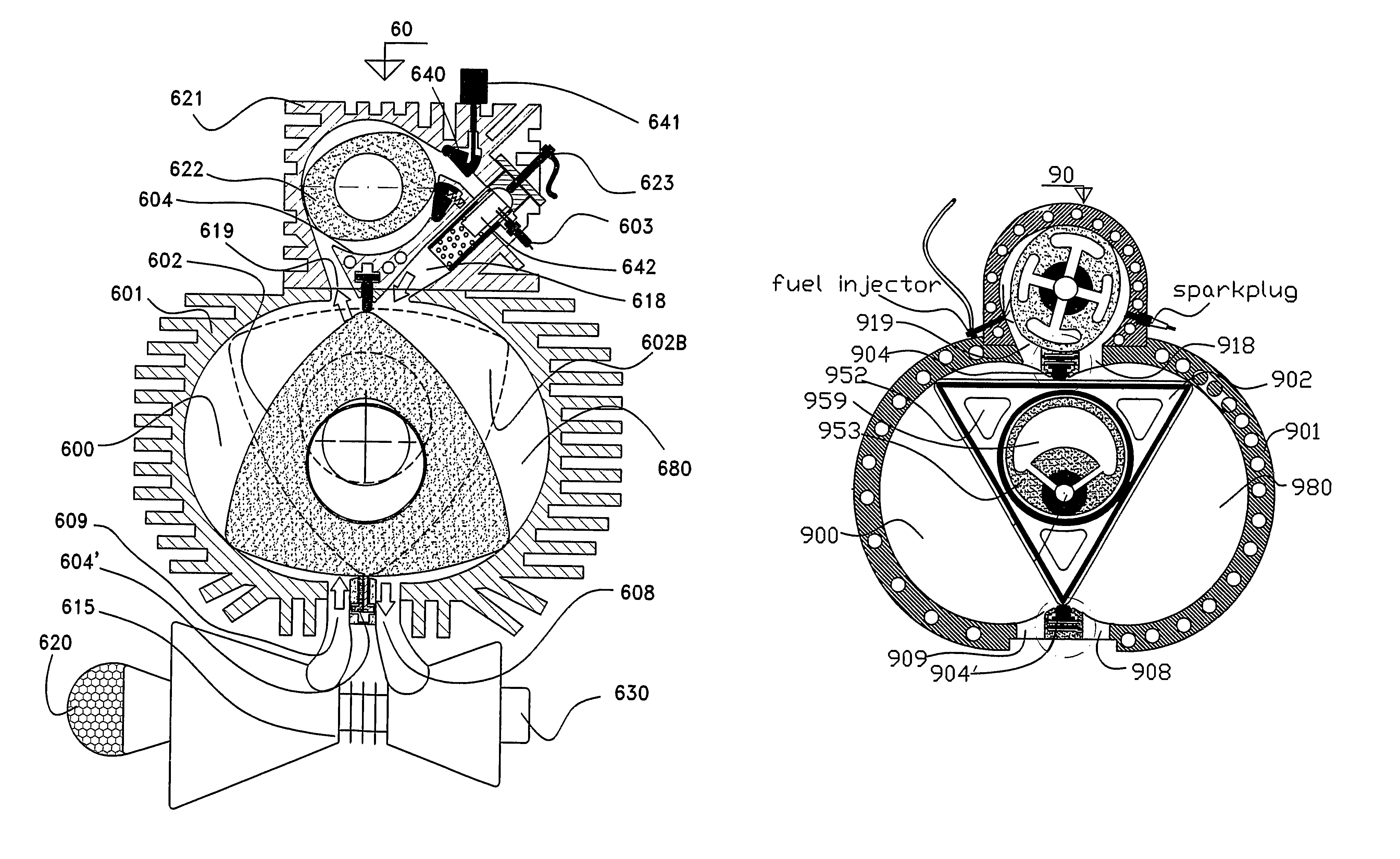
[0045]b) Second rotary device that is connected to the first rotary device in order to operate together and to achieve higher power output and to further smooth the operation,
[0061]In a preferred embodiment of the present invention the sector, buffer-seals, are equipped with a bounce dumping system in order to improve sealing and therefore adequate separation between the two sectors of the inside housing volumes.
[0063]In another preferred embodiment of the present invention, the engine is a fully rotational, concentric, volumetric system that functionally integrates with the other components of the present invention, in order to avoid the disadvantages of the eccentric, complex motion of the Wankel volumetric system.

Problems solved by technology

After many years of Wankel engine development, there are some practical limitations that prevent its widespread acceptance, despite its theoretical advantages with respect to a reciprocating piston engine.
Consequently, only a limited number of manufacturers are involved with Wankel engine production.
Some of the Wankel rotary engine limitations relate to its rotor apex seals, as expressed by the following characteristics:Tendency to bounce over housing internal contour;Incompatibility of a suitable material for the apex seal with that of the rotor housing;Damage to the internal contour of the rotor housing and to the seals;Speed limitations due to high centrifugal forces;Poor sealing at a low rotational speed and under sudden changes of operational conditions such as acceleration and deceleration and of engine load; andSealing limitations of the apex seal when the engine is exposed to a relatively high pressure, which is characteristic of Diesel engines.
All of the above-mentioned limitations result in inadequate sealing that leads to low reliability and short duration of operation, defined also as a short time between overhauls (TBO).
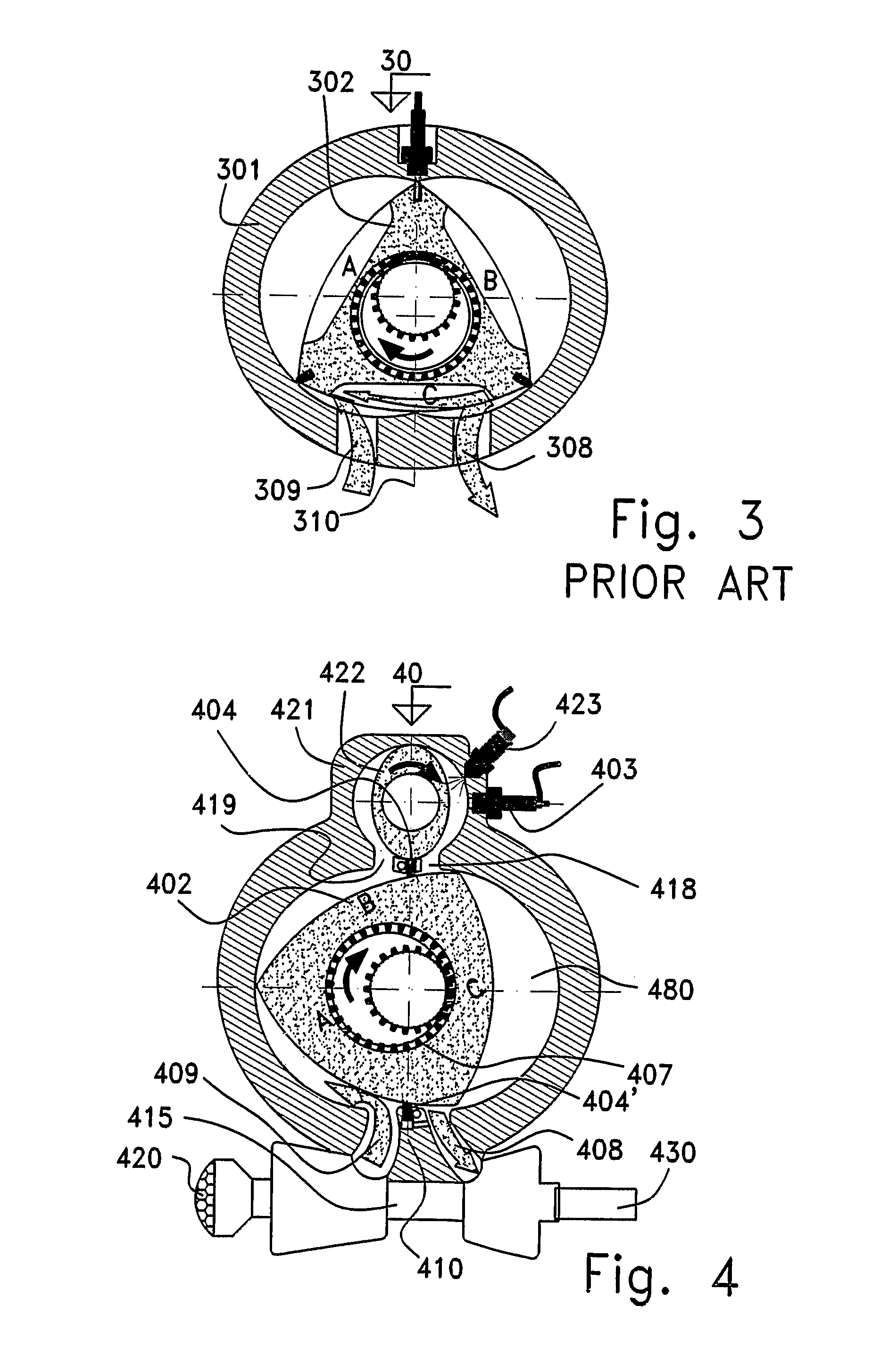
Other known drawbacks of prior art Wankel rotary engines are:The combustion chamber is not optimally configured for its function, and is therefore one of the main reasons for its inability in achieving efficient combustion and for its relatively low thermal efficiency.A tendency to mix intake charge with burnt exhaust gases during exhaust-intake overlap, which reduces engine efficiency and output.
The utility of a turbocharger, which further mixes the intake charge with the exhaust gases, is reduced since a greater percentage of the burnt gas is forced thereby to remain in the engine, to drift by the motor rotor to the intake section thereof, and to mix with the intake charge.A high surface to volume ratio, resulting in fuel condensation on the inner walls of the working volumes, which is particular noticeable in water-cooled engines and negatively influences efficiency and wear.At the beginning of each work cycle, a noticeable conflict is characteristic of prior art Wankel engines resulting in inefficient utilization of combustion products, between the geometrical position of the rotor during ignition to the direction of the driving forces generated by the combustion products.
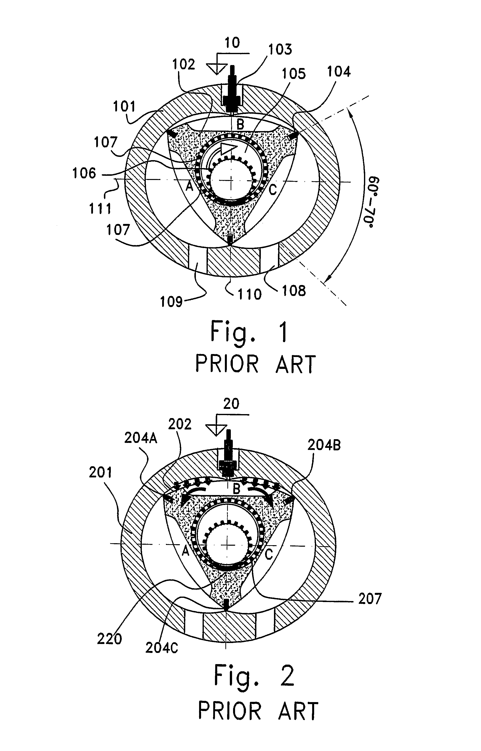
When the leaning angle is approximately 60 degrees, substantially all of the combustion forces support the rotation of the rotor; however, the remaining pressure of the combustion products is very low at such a leaning angle indicating that the work cycle is about to end.In addition to the previously mentioned conflict, substantially all of the combustion pressure is generated, immediately after ignition, over the rotor and perpendicularly to the main shaft, imposing a very high load and stress to the engine system which must be taken into consideration during the engine system design.The effective work cycle sector of prior art Wankel engine is considerably narrow, beginning after an apex of the rotor has passed the minor axis by about 60 degrees and ending after about 60 degree of rotation, where the same apex reaches the point which start to expose the exhaust port.The compression ratio of prior art Wankel rotary engine depends on the K factor (defined as ratio of the rotor radius to eccentricity).
In order to achieve reasonably good results with a prior art Wankel engine, limiting compromises must be made.The eccentric motion of the rotor drive system assembly of the Wankel engine results in restrictions to engine speed, and poses dynamic balancing problems.
The complex motion of the rotor and the eccentric shaft assembly results in a shaft speed three times higher than that of the rotor, thereby resulting in a low torque-high speed engine shaft power take off (P.T.O.)

Method used


Image

  • Wankel and similar rotary engines
  • Wankel and similar rotary engines
  • Wankel and similar rotary engines

Examples


Embodiment Construction

[0102]The present invention is a novel rotary engine configuration having at least one rotor and at least one rotating combustion chamber flow control device (CCFC), the rotation of which is synchronized with the rotation of each rotor. Two stationary buffer seals located at the two ends of the minor axis of the rotor housing divide the latter into two separate volumes, a first intake and compression volume and a second expansion and exhaust volume downstream to the first volume. Each CCFC receives compressed oxygenated fluid from the intake volume, injects fuel into the compressed fluid, ignites an air-fuel mixture, and transfers the combustion products to the expansion volume.

[0103]To appreciate the utility of the engine configuration of the present invention, reference is first made to FIGS. 1-3, which illustrate several limitations of prior art Wankel rotary engines.

[0104]FIG. 1 illustrates the configuration of an exemplary prior art Wankel rotary engine generally indicated at 1...


PUM


Abstract

An improved rotary engine system has two stationary buffer seals located at the two ends of the minor axis of a rotor housing that divide the rotor housing into two separate volumes. A first volume is an intake and compression volume and a second volume downstream to the first volume is an expansion and exhaust volume. A rotating combustion chamber flow control device (CCFC) is synchronized with a rotor, for receiving compressed fluid from the first volume, for receiving fuel injected by a fuel injector located within a corresponding CCFC, for igniting and burning an air-fuel mixture, to allow combustion products to expand in the second volume, and for transferring the combustion products to the second volume. In one embodiment, the CCFC is synchronized with two longitudinal shafts fitted at centers of first and second housings, respectively, in each of which are located a pair of side by side rotors.

Description

CLAIM OF PRIORITY[0001]This application claims priority as a 371 of international application serial number a 371 of international patent application serial number PCT / IL2006 / 000911, filed on Aug. 7, 2006 which claims priority to Israeli patent application number 170165, filed on Aug. 8, 2005.FIELD OF THE INVENTION[0002]The present invention relates in general to rotary engines. In particular, the present invention relates to improvements in Wankel and similar rotary engines which, by being applied to a prior art engine, significantly raises its power output and efficiency and enables a more advanced cycle.BACKGROUND OF THE INVENTION[0003]The manufacturers of Wankel rotary engines have attempted to provide an internal combustion engine that overcomes most of the drawbacks of a reciprocating piston engine, while operating very smoothly and having a high power to weight ratio and a higher rotational speed with respect to a reciprocating piston engine. After many years of Wankel engine...

Claims


Application Information

Patent Timeline
Patent Type & Authority Patents(United States)
IPC IPC(8): F02B53/08F02B53/04F01C1/02
CPCF01C1/22F01C11/008F02B53/02Y02T10/17Y02T10/12F02B53/00F02B75/12F01C1/02
Inventor ROM, HAIMROM, TAL
Owner ROM HAIM
Learn More