
Controlling the bends in a fiber optic cable to eliminate measurement error in a scanning terahertz sensor

a technology of fiber optic cable and sensor, applied in the field of scanning sensors, can solve the problems of reducing the accuracy of the sheet material produced, affecting the accuracy of the sample obtained for testing, and often not being practicable, so as to reduce or eliminate the measurement errors of the sensor, and minimize the variations in temporal delays

Active Publication Date: 2012-11-20
HONEYWELL ASCA INC
View PDF18 Cites 2 Cited by
  • Summary
  • Abstract
  • Description
  • Claims
  • Application Information

AI Technical Summary

Benefits of technology

"The present invention is about a scanning sensor system that uses THz technology to measure properties of a sample in real-time industrial processes. The system includes a mobile carriage with a transmitter and a detector, a laser source, and an optical fiber cable to deliver the optical pulses to the sample. The system also includes a take-up mechanism to control the movement of the fiber optic cables to minimize variations in temporal delays and measuring errors. The technical effects of the invention include improved accuracy and consistency of the sensor readings, reduced errors caused by bending and temperature gradients, and improved efficiency in detecting and measuring the sample's characteristics."

Problems solved by technology

Although various properties of sheet materials can be detected by off-line laboratory testing, this procedure is often not practical because of the time required for sample acquisition and analysis.
Also, laboratory testing has the shortcoming that samples obtained for testing may not accurately represent sheet material that has been produced.
As the T-rays pass through the object under test, they are typically distorted.
Typical THz-TDS devices are designed for batch applications and therefore are not suitable for deployment for on-line applications.

Method used


Image

  • Controlling the bends in a fiber optic cable to eliminate measurement error in a scanning terahertz sensor
  • Controlling the bends in a fiber optic cable to eliminate measurement error in a scanning terahertz sensor
  • Controlling the bends in a fiber optic cable to eliminate measurement error in a scanning terahertz sensor

Examples


Embodiment Construction

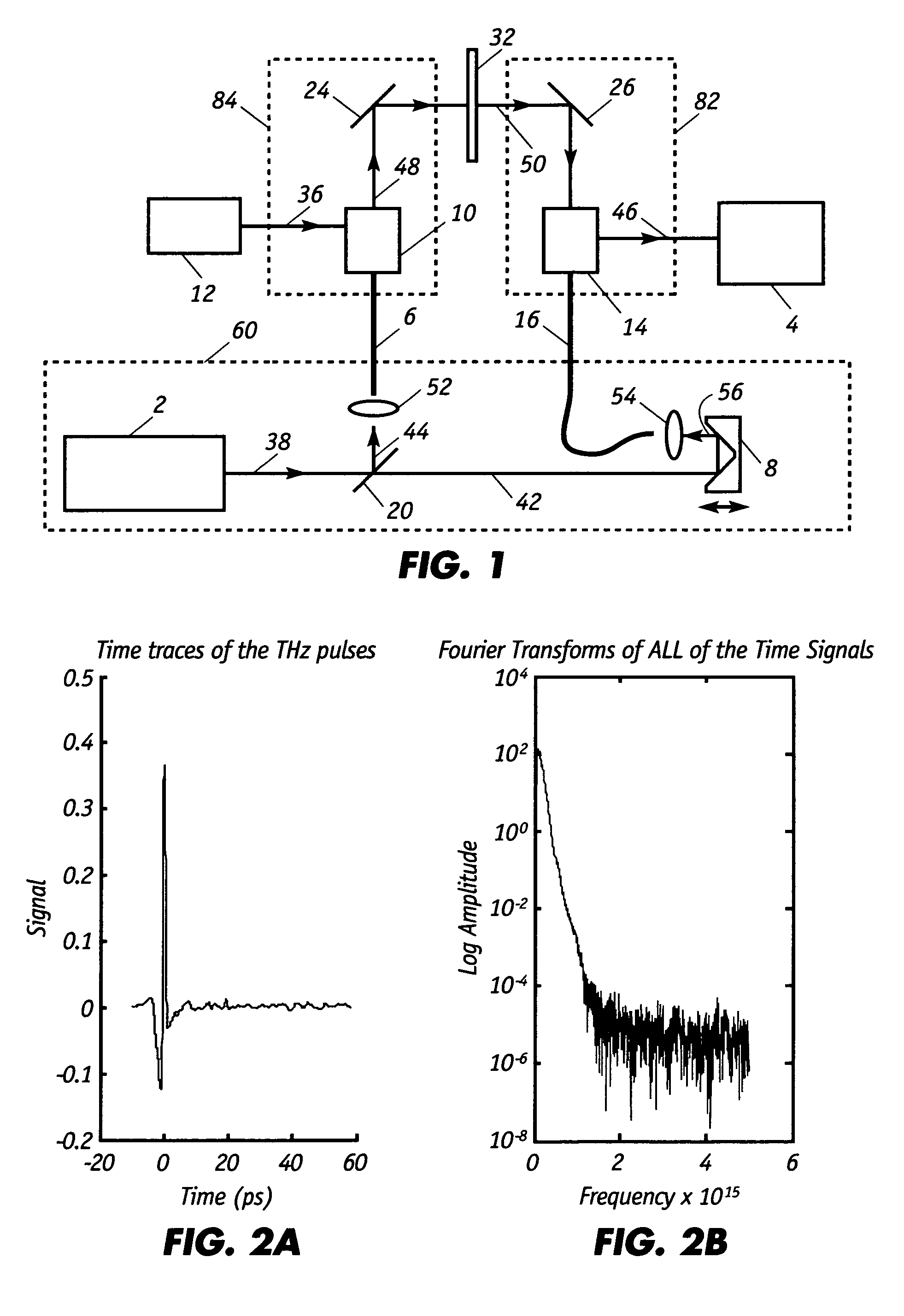
[0041]FIG. 1 shows the structure of a terahertz time-domain spectrometer for monitoring at least one property of the moving sheet or web of material 32. The basic components of the spectrometer include: pulsed laser source 2, beam splitter 20, terahertz transmitter 10, modulated power source 12, terahertz receiver or detector 14, spectroscopic analyzer 4, and optical delay device 8, each of which consists of a conventional device. Pulsed laser source 2, such as a femto-second pulse laser, generates pump signals 38 that are directed toward beam splitter 20 which splits the light pulses of pump signal 38 to yield excitation light 44 and detector gating light 42.

[0042]Excitation light 44 is focused by objective lens 52 and launched into and transmitted through delivery fiber optic cable or optical fiber 6. Excitation light 44 illuminates transmitter 10 to generate terahertz radiation or T-rays 48 which are directed by mirror 24 into moving sheet 32. Modulated power source 12 supplies a...


PUM

PropertyMeasurementUnit
cross-directional distancesaaaaaaaaaa
widthaaaaaaaaaa
distanceaaaaaaaaaa

Abstract

A terahertz time-domain spectrometer scanning sensor system includes a transmitter and a receiver that are secured to a mobile scanner head. Optical pump light, in the form of short pulses launched from a stationary laser located remotely from the scanner head, is delivered to the transmitter and receiver through a controlled fiber optic cable arrangement so that variations in temporal pulse relays that are associated fiber optic transmission are minimized. In this fashion, the movement of the fiber optic cable is maneuvered along a defined path so as to control the bends in the cable and thus minimize variations in temporal delays that can otherwise arise as the pulses of light are transmitted through the fiber. Pulses of laser light launched from the laser into the optical fiber will exit the cable with consistent (i) time of arrival, (ii) phase duration, and (iii) polarization state and energy.

Description

REFERENCE TO RELATED APPLICATIONS[0001]This application claims priority to U.S. Provisional Application 61 / 009,647 that was filed on Dec. 31, 2007.FIELD OF THE INVENTION[0002]The present invention generally relates to scanning sensors that employ terahertz radiation for detecting the presence of specific components in paper and other sheet products. In particular, the technique employs a terahertz time-domain spectrometer whereby optical pump light, in the form of short pulses from a laser, is delivered to the transmitter and receiver through a controlled fiber optic cable arrangement so that variations in temporal pulse delays that would otherwise arise as the pulses of light are transmitted through the fiber optic cable are minimized or eliminated.BACKGROUND OF THE INVENTION[0003]It is often desirable to obtain measurements of selected characteristics of sheet materials during manufacture. Although various properties of sheet materials can be detected by off-line laboratory testin...

Claims


Application Information

Patent Timeline
Patent Type & Authority Patents(United States)
IPC IPC(8): G01N21/01
CPCG01J3/02G01J3/0218G01J3/42G01N21/86G01N21/3586G01N2021/8609
Inventor HARAN, FRANK MARTINMACHATTIE, ROSSBESELT, RON EJEZ, DAVID
Owner HONEYWELL ASCA INC
Learn More