System, method and program product for cable loss compensation in an electrical submersible pump system

a submersible pump and cable loss compensation technology, applied in the field of electrical submersible pump systems, can solve the problems of not being able to provide the proper rated motor voltage of the v/hz curve, not being able to adjust the output voltage of the variable speed drive with the operating frequency, and not being able to meet the needs of the operation

Active Publication Date: 2012-11-20
BAKER HUGHES INC
View PDF18 Cites 9 Cited by
  • Summary
  • Abstract
  • Description
  • Claims
  • Application Information

AI Technical Summary

Benefits of technology

[0010]Accordingly, embodiments of the present invention provide a method, system, and program product to control voltage at the motor terminals under varying conditions by actively modifying the output voltage of the variable speed drive to compensate for cable loss in the ESP system. Embodiments of the present invention advantageously utilize algorithms to optimize output voltage of the variable speed drive in an ESP system, which include compensating for cable loss using the motor current and the complex impedance of the cable.

Problems solved by technology

The approaches of the prior art are not responsive to all changes in well conditions.
In that case, varying the output voltage of the variable speed drive with the operating frequency according to either a linear or “shaped” V / Hz curve fails to provide the proper rated motor voltage because the frequency, that is, the RPM, is constant and under the prior art the voltage from the variable speed drive is maintained, despite the motor load changing.
However, the change in the motor load results in a change in the motor current, which in turn results in a change in the voltage drop in the cable.
Because the motor can be a very long distance from the variable speed drive, a change in the voltage drop in the cable can be very significant.
The end result is a change in the motor terminal voltage, which can cause various problems as understood by those skilled in the art.

Method used


Image

  • System, method and program product for cable loss compensation in an electrical submersible pump system
  • System, method and program product for cable loss compensation in an electrical submersible pump system
  • System, method and program product for cable loss compensation in an electrical submersible pump system

Examples


Embodiment Construction

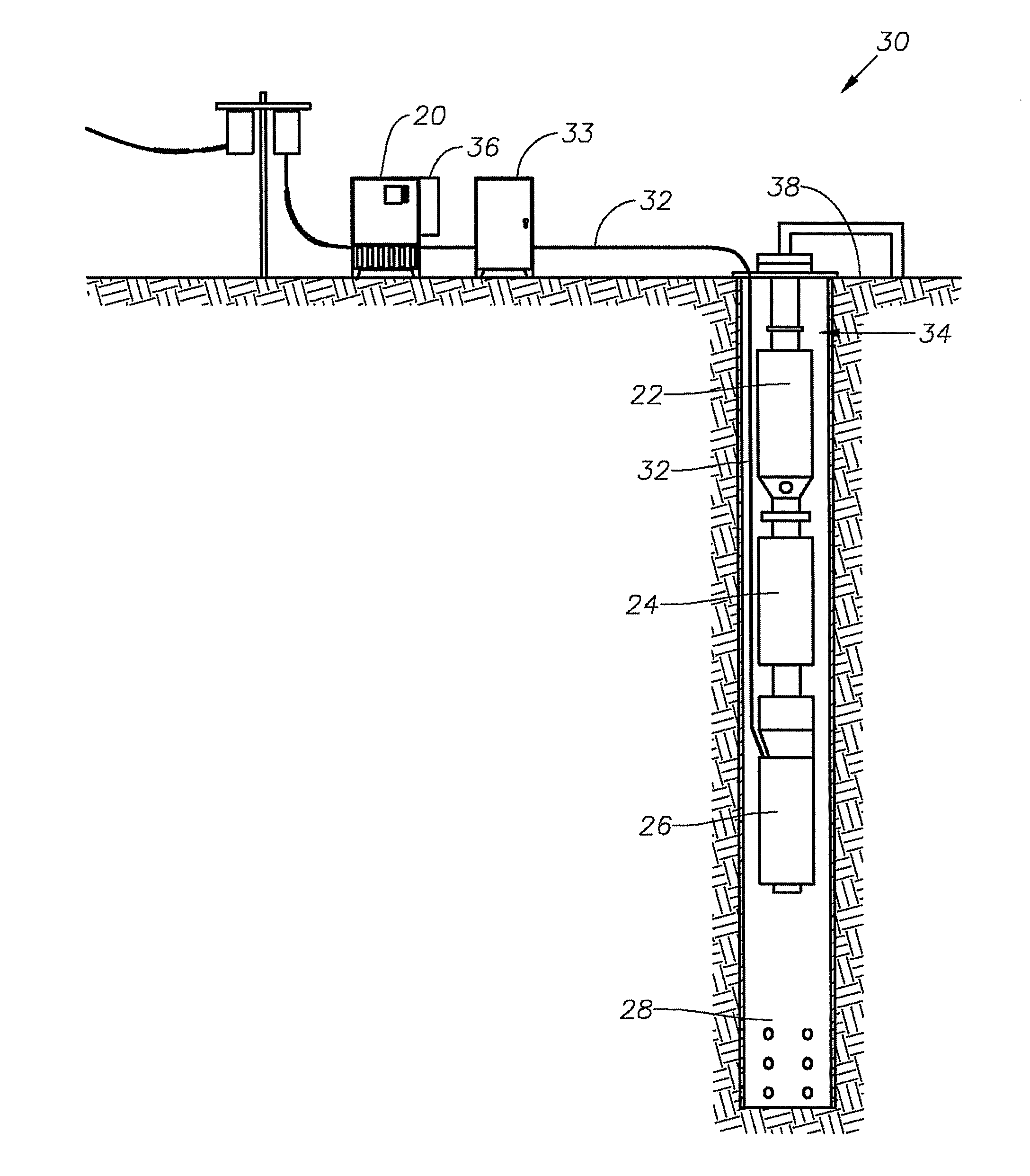
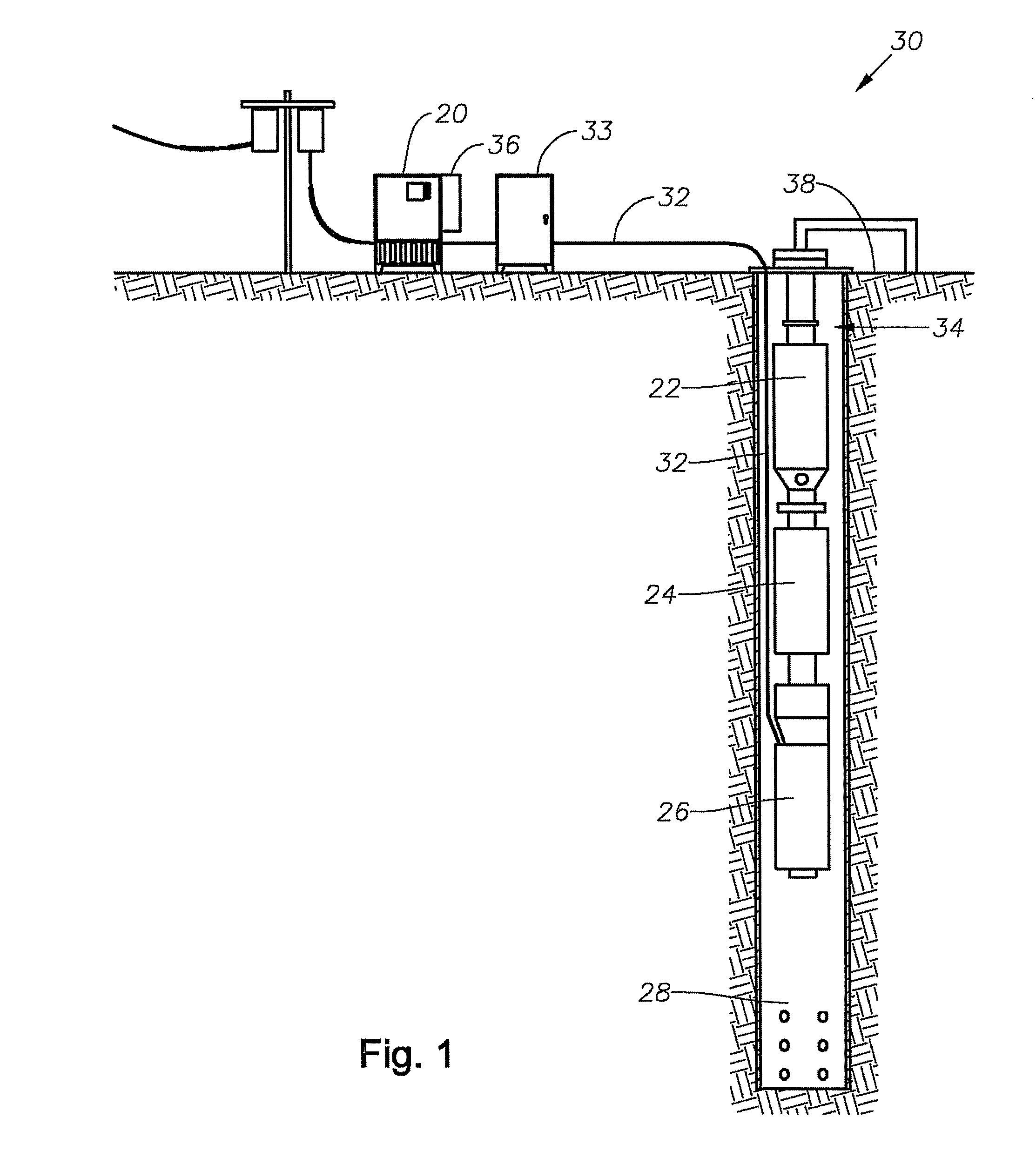
[0019]The present invention will now be described more fully hereinafter with reference to the accompanying drawings in which embodiments of the invention are shown. This invention may, however, be embodied in many different forms and should not be construed as limited to the illustrated embodiments set forth herein; rather, these embodiments are provided so that this disclosure will be thorough and complete, and will fully convey the scope of the invention to those skilled in the art. Like numbers refer to like elements throughout.

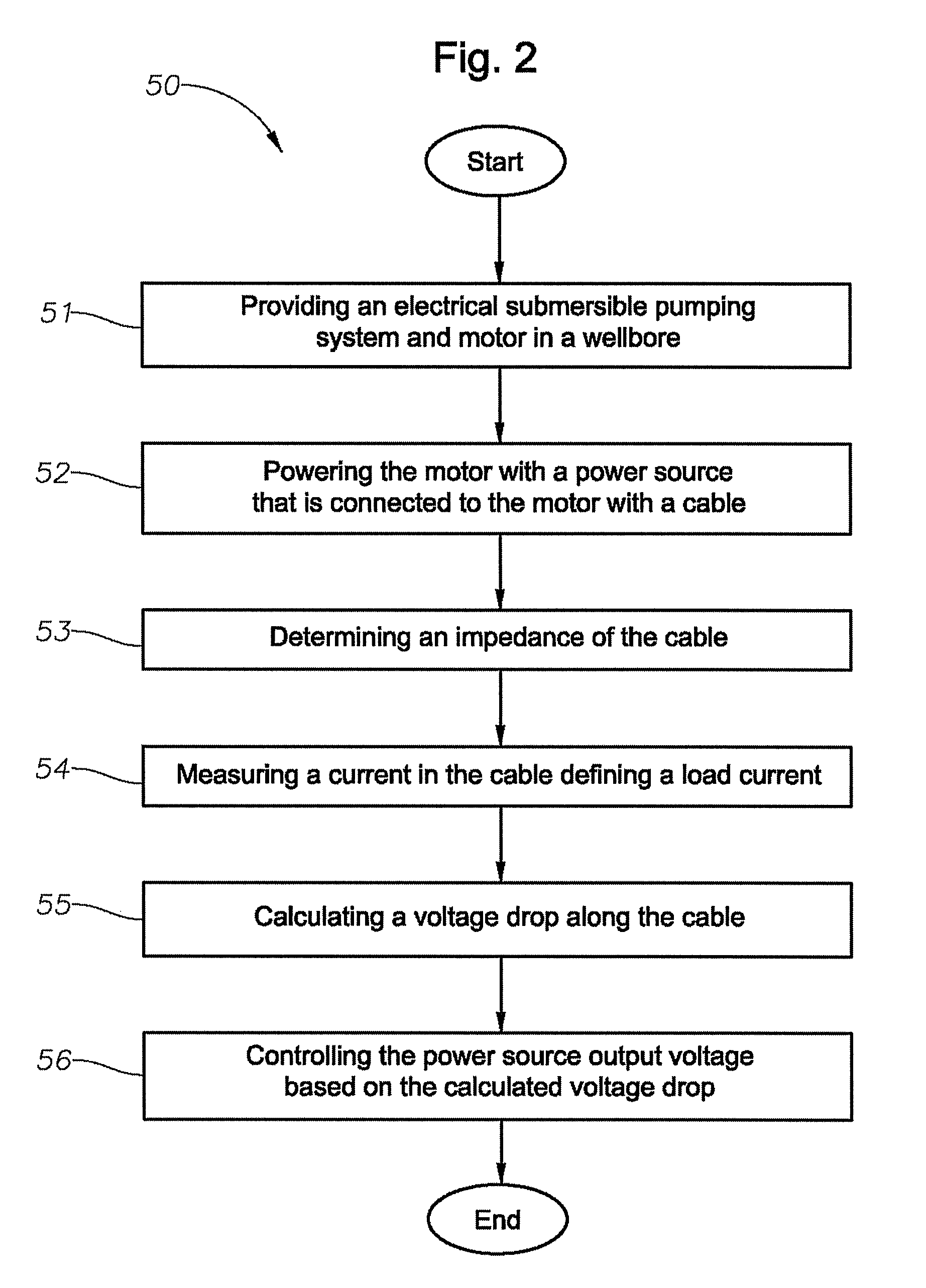
[0020]Applicants recognize deficiencies in the prior art approaches of varying the output voltage of the variable speed drive with the operating frequency to fit a linear or “shaped” V / Hz curve. The approaches of the prior art are not responsive to all changes in well conditions, and Applicants recognize the prior art approach as a source of the problem. Applicants further recognize the need to actively modify an output voltage of the variable speed drive...


PUM


Abstract

An electrical submersible pumping (ESP) system can include a pump located in a wellbore, a motor attached to the pump, a power source located at the surface, a cable electrically coupling the power source and the motor, and a current sensor. The ESP system can also include a controller communicating with the current sensor to calculate a voltage drop associated with the cable responsive to an impedance of the cable. The controller can also control a power source output voltage responsive to the calculated voltage drop. For example, the controller can adjust the power source output voltage to minimize a cable current while maintaining a minimum motor voltage. The controller can also control a motor shaft speed by changing a power source output voltage frequency to compensate for changing slip and adjust the power source output voltage to minimize the cable current while maintaining a minimum motor voltage.

Description

RELATED APPLICATIONS[0001]This application claims priority to and the benefit of U.S. Provisional Patent Application Ser. No. 61 / 035,764, by Yohanan et al., titled “System, Method and Program Product for Cable Loss Compensation in an Electrical Submersible Pump System”, filed Mar. 12, 2008, incorporated herein by reference in its entirety.BACKGROUND[0002]1. Field of Invention[0003]The present invention relates in general to electrical submersible pump (ESP) systems and, in particular, to an improved system, method, and program product for controlling motor terminal voltage under varying load conditions by compensating for cable loss.[0004]2. Background[0005]Electrical submersible pumping (ESP) systems are often used in hydrocarbon producing wells for pumping fluids from within the wellbore to the surface. Within this specification, the term wellbore includes oil wells, gas wells, geothermal wells, carbon sequestration wells, and others as understood by those skilled in the art. A ty...

Claims


Application Information

Patent Timeline
Patent Type & Authority Patents(United States)
IPC IPC(8): H02P7/00
CPCH02P23/08E21B43/128H02P27/047E21B47/008
Inventor YOHANAN, TOM G.KNOX, DICK L.LEUTHEN, JOHN M.LAYTON, JIM E.THOMPSON, HOWARD G.
Owner BAKER HUGHES INC
Why Eureka
Try Eureka