
Motor vehicle tire having tread pattern

a technology for motor vehicles and tires, applied in vehicle components, non-skid devices, transportation and packaging, etc., can solve the problems of difficult to solve, worsen the rolling noise of tires, and noise of tyres, and achieve low noise level values, high comfort, and high grip

Inactive Publication Date: 2012-11-27
PIRELLI TYRE SPA
View PDF23 Cites 4 Cited by
  • Summary
  • Abstract
  • Description
  • Claims
  • Application Information

AI Technical Summary

Benefits of technology

The tire achieves low noise levels both inside and outside the vehicle, improved grip on wet roads, reduced braking distances, and enhanced handling on dry roads, maintaining optimal grip and comfort during high-speed maneuvers.

Problems solved by technology

The noisiness of tyres is a problem which is difficult to solve because some measures which tend to reduce it adversely affect the directional, tractional and water drainage properties.
However, transverse grooves which are very inclined worsen the rolling noise of the tyre.
Therefore, it is not possible to obtain a low noise level both inside and outside the car and it is difficult to achieve in each case the best possible compromise.
However, the inventors of the present invention have perceived that the presence of a considerable number of inclined grooves leading into a longitudinal groove, and their arrangement close to each other, adversely affects the rolling noise of the tyre.

Method used


Image

  • Motor vehicle tire having tread pattern
  • Motor vehicle tire having tread pattern
  • Motor vehicle tire having tread pattern

Examples


Embodiment Construction

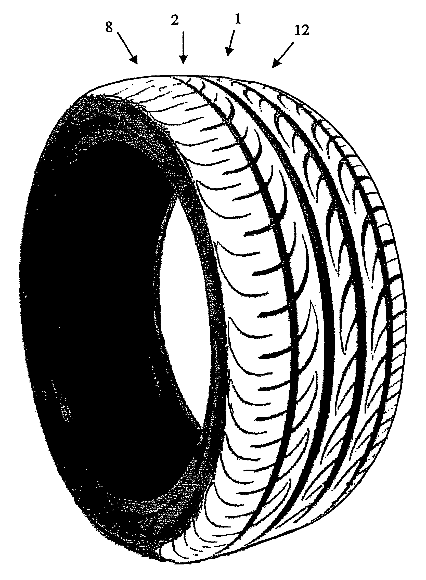
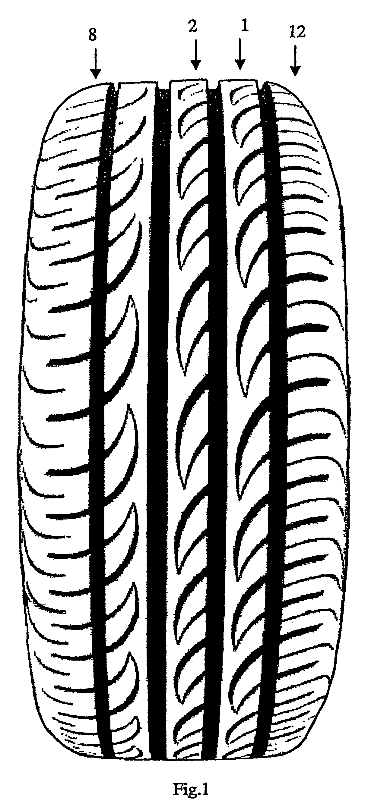
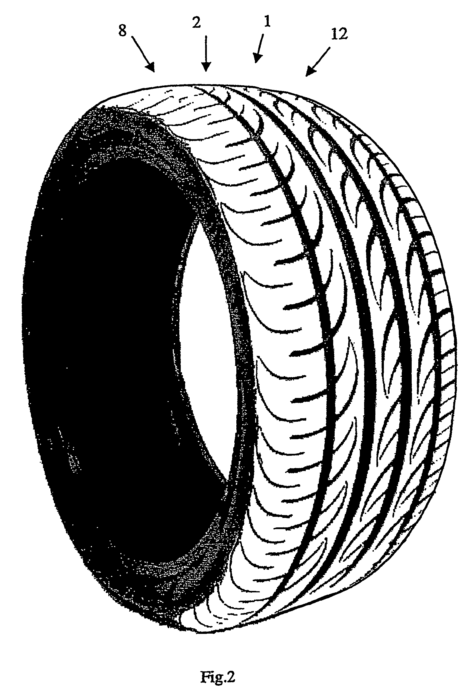
[0060]FIGS. 1 and 2 show a tyre 1 with a tread 2 axially delimited by two shoulders 8 and 12. The tread 2 is provided with circumferential grooves 3, 4, 5 and 6 (FIG. 3) which extend in longitudinal direction and are parallel to an equatorial plane 7 of the tyre. The tread 2 includes three circumferential rows of blocks 9, 10 and 11, a central row 10 and two lateral rows 9 and 11. The shoulder 8 is separated from the row of blocks 9 by means of the circumferential groove 3. The row of blocks 9 is located between the circumferential grooves 3 and 4. The row of blocks 10 is located between the circumferential grooves 4 and 5. The row of blocks 11 is located between the circumferential grooves 5 and 6. The shoulder 12 is separated from the row of blocks 11 by means of the groove 6.

[0061]The shoulders 8 and 12 comprise an axially internal region 108 and 112, respectively, said axially internal region being closer to the equatorial plane and influencing the performance of the tyre, and a...


PUM


Abstract

A tire tread includes a circumferential row of blocks disposed between first and second circumferential grooves, wherein each of the blocks is delimited by a section of the first circumferential groove and by first and second transverse grooves that extend from the first circumferential groove and terminate at a common vertex spaced from the second circumferential groove. The common vertex is separated from the second circumferential groove by a continuous circumferential tread rib. The second transverse groove delimits a first one of the blocks and is separated from the first transverse groove that delimits a circumferentially adjacent block by a solid tread portion. The solid tread portion extends from the first circumferential groove to the continuous circumferential tread rib, and the solid tread portion forms a single body with the continuous circumferential tread rib, spacing the first block and the circumferentially adjacent block from each other.

Description

[0001]This application is a continuation of U.S. application Ser. No. 10 / 473,304, filed Mar. 9, 2004 now U.S. Pat. No. 7,484,543, which is a national phase entry under 35 U.S.C. §371 from PCT International Application No. PCT / EP02 / 02552, filed Mar. 8, 2002, in the European Patent Office, the contents of which are relied upon and incorporated herein by reference. In addition, Applicants claim the benefit of priority under 35 U.S.C. §119(a)-(d) based on European Patent Application No. 01201232.4, filed Mar. 30, 2001, in the European Patent Office, and the benefit of priority under 35 U.S.C. §119(e) of U.S. Provisional Application No. 60 / 280,762, filed Apr. 3, 2001. The subject matter of the disclosures of U.S. application Ser. No. 10 / 473,304, PCT International Application No. PCT / EP02 / 02552, European Patent Application No. 01201232.4, and U.S. Provisional Application No. 60 / 280,762, is incorporated herein by reference.BACKGROUND[0002]1. Field of the Disclosure[0003]The present inventi...

Claims


Application Information

Patent Timeline
Patent Type & Authority Patents(United States)
IPC IPC(8): B60C11/03B60C11/04B60C11/11B60C11/13
CPCB60C11/0302B60C11/0306B60C11/0309B60C11/042B60C11/11B60C11/03B60C11/13B60C2011/0388B60C2011/0383Y10S152/901B60C2011/0374B60C11/04B60C2011/0381B60C11/0304B60C11/033
Inventor COLOMBO, GIANFRANCOCUCCO, GIANCARLOBELLO, VITO
Owner PIRELLI TYRE SPA
Learn More