Apparatus and method for positioning an object in a building

a technology for lifting apparatuses and buildings, applied in the direction of load-engaging elements, transportation and packaging, etc., can solve the problems of inconvenient use of apparatuses, difficulty in maneuvering reinforced concrete panels, and death, so as to facilitate less time consumption, less expense, and convenient and safe placement

Active Publication Date: 2012-11-27
SCHUYLEMAN JAY WESLEY
View PDF15 Cites 21 Cited by
  • Summary
  • Abstract
  • Description
  • Claims
  • Application Information

AI Technical Summary

Benefits of technology

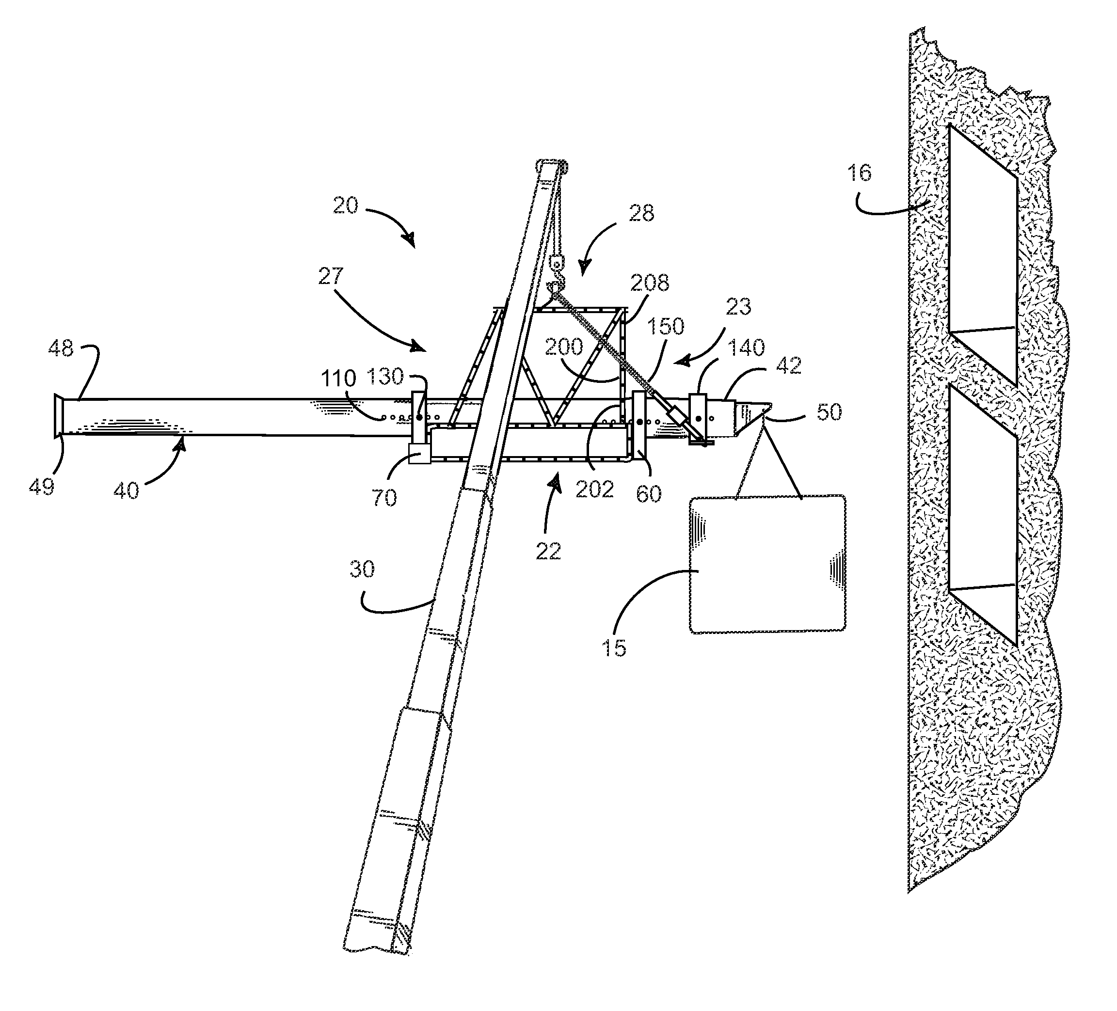
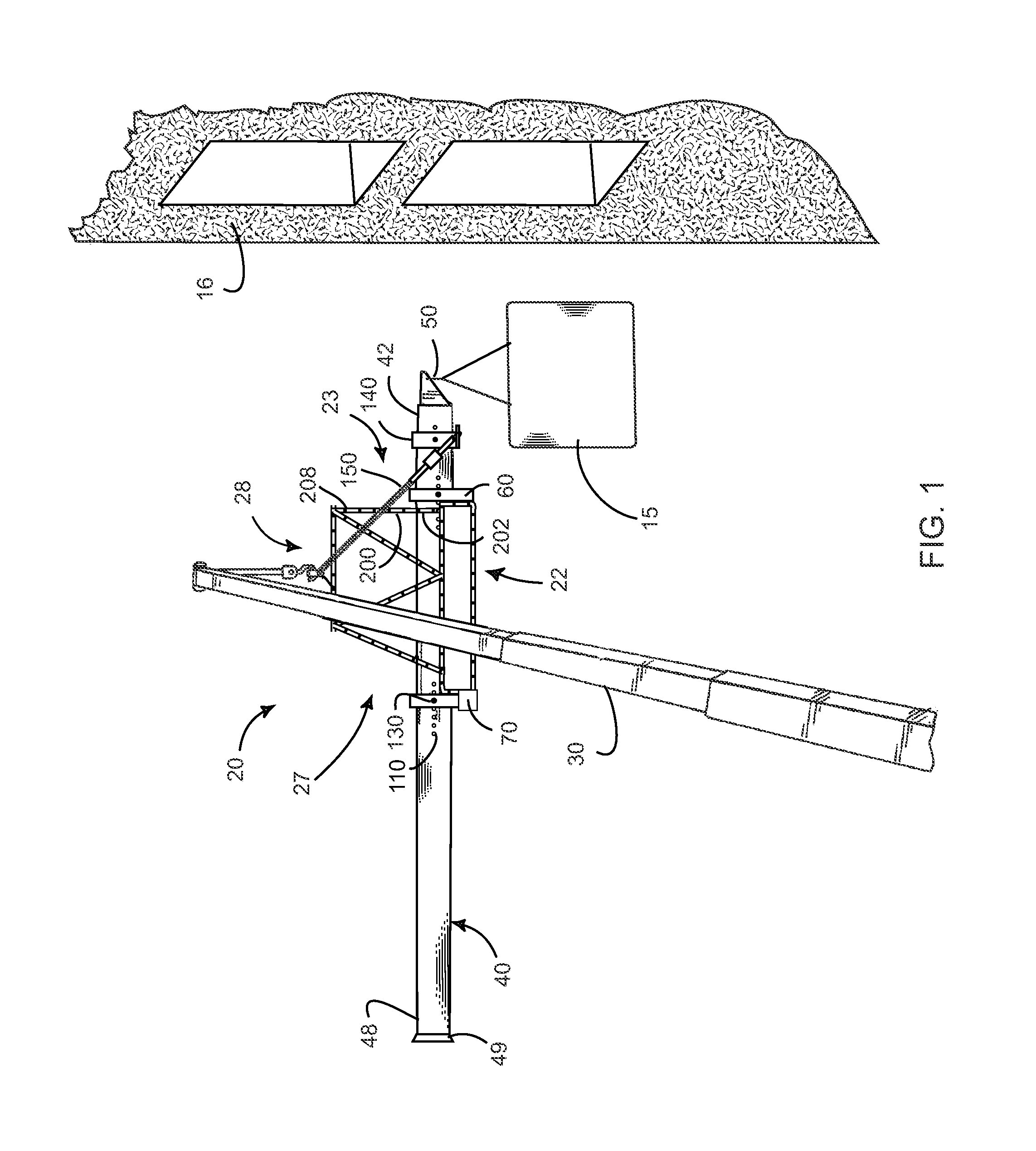
[0013]The present apparatus facilitates less time consumption and less expense in positioning the load such as a precast panel in an opening of the building. Such an apparatus selectively positions the load at a desired distance inside the opening without pulling the precast panel by the workers. Moreover, the apparatus is easier and safer to place the precast panel in a recessed opening of the building. Other features and advantages of the present invention will become apparent from the following more detailed description, taken in conjunction with the accompanying drawings, which illustrate, by way of example, the principles of the invention.

Problems solved by technology

Maneuvering of reinforced concrete panels is difficult since such panels with large dimensions are extremely heavy.
Further, if the panel is large and heavy, the workers must manually pull the panel into the opening.
The workers pulling the panel into the opening may therefore accidentally fall and, unfortunately, may get killed.
Such an apparatus is inconvenient for use due to the exact four feet distance of the panel from the crane attachment, which prevents the adjustment of the distance of the panel from the apparatus as desired.
The shortcomings of the apparatus are that the process of positioning the panel in the opening of the building is complex and time consuming.
Moreover, since the workers must be paid for installing the panel in the building, the expense may rise if the process is time consuming.

Method used


Image

  • Apparatus and method for positioning an object in a building
  • Apparatus and method for positioning an object in a building
  • Apparatus and method for positioning an object in a building

Examples


Embodiment Construction

[0019]Illustrative embodiments of the invention are described below. The following explanation provides specific details for a thorough understanding of and enabling description for these embodiments. One skilled in the art will understand that the invention may be practiced without such details. In other instances, well-known structures and functions have not been shown or described in detail to avoid unnecessarily obscuring the description of the embodiments.

[0020]Unless the context clearly requires otherwise, throughout the description and the claims, the words “comprise,”“comprising,” and the like are to be construed in an inclusive sense as opposed to an exclusive or exhaustive sense; that is to say, in the sense of “including, but not limited to.” Words using the singular or plural number also include the plural or singular number respectively. Additionally, the words “herein,”“above,”“below” and words of similar import, when used in this application, shall refer to this appli...


PUM


Abstract

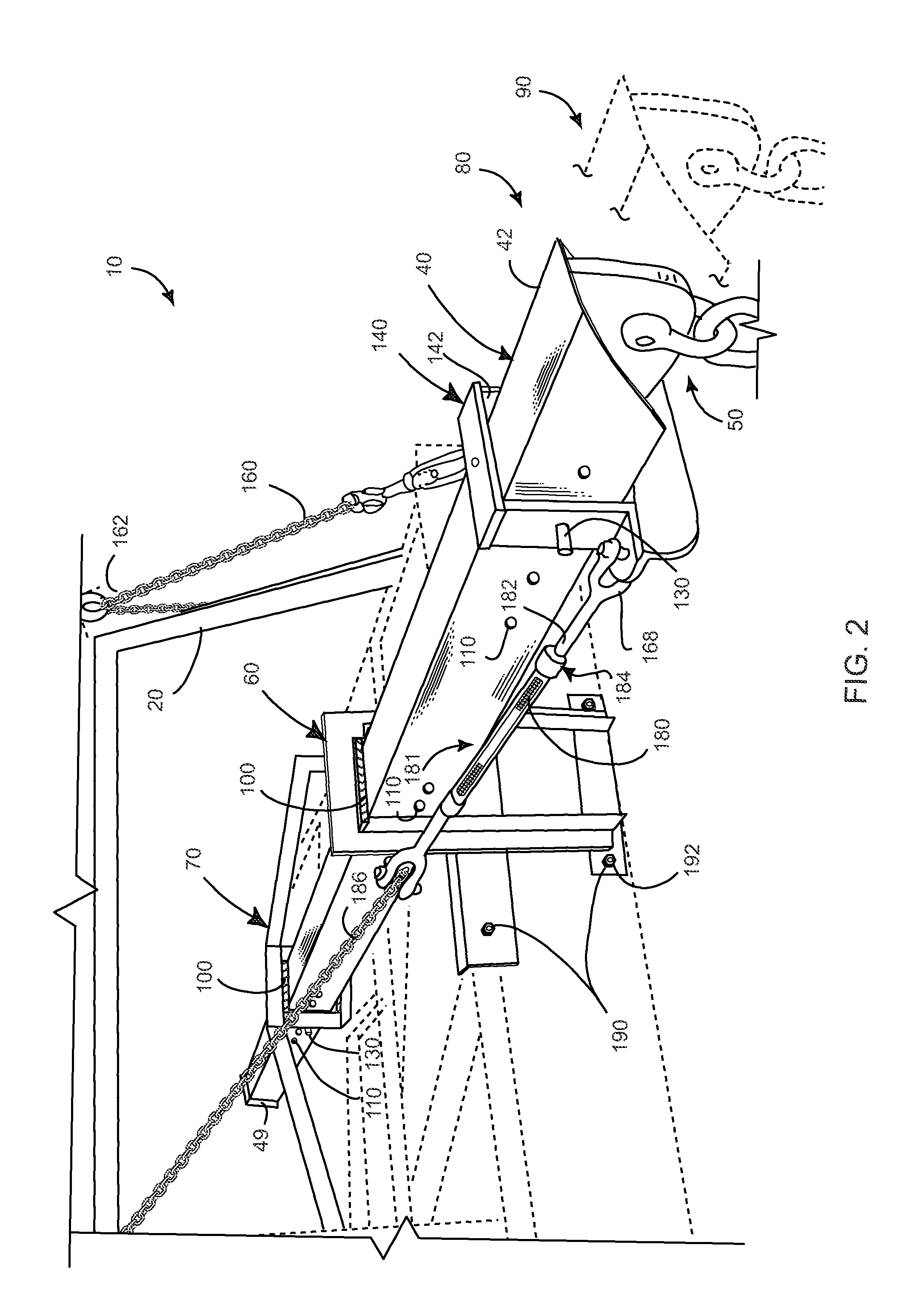
An offset hoisting apparatus comprises a rigid boom having a hook at a distal end thereof. The offset hoisting apparatus further includes a front mount having a front boom aperture and a rear mount having a rear boom aperture, each being adapted for confining the boom to slidably move therethrough. The invention has a slip collar having a slip collar boom aperture therein for receiving the boom therethrough and an offset hoisting apparatus attachment having a flexible linkage fixed at a distal end thereof with the slip collar. The boom is selectively slid between a retracted and an extended position and the load is secured to the hook. The crane apparatus then lifts and positions the load to a building.

Description

CROSS-REFERENCE TO RELATED APPLICATIONS[0001]This application claims the benefit of U.S. Provisional Patent Application 61 / 090,972, filed on Aug. 22, 2008, and incorporated herein by reference.STATEMENT REGARDING FEDERALLY SPONSORED RESEARCH AND DEVELOPMENT[0002]Not Applicable.FIELD OF THE INVENTION[0003]This invention relates to a hoisting apparatus, and more particularly to an apparatus for use with a crane in positioning an object at a desired distance inside an opening of a building.DISCUSSION OF RELATED ART[0004]Tall buildings are generally constructed as a shell with openings for panels and windows or the like. Precast or prefabricated panels are then placed within these openings which are usually finished before installation. Columns and beams are the most common precast concrete structures constructed in a factory and later transported to the site. Maneuvering of reinforced concrete panels is difficult since such panels with large dimensions are extremely heavy. There have b...

Claims


Application Information

Patent Timeline
Patent Type & Authority Patents(United States)
IPC IPC(8): B66C1/10B66C1/00
CPCB66C1/105
Inventor SCHUYLEMAN, JAY WESLEY
Owner SCHUYLEMAN JAY WESLEY
Why Eureka
Try Eureka