Coaxial connector with shielding shell

a shielding shell and coaxial connector technology, applied in the direction of coupling device connection, two-part coupling device, electrical apparatus, etc., can solve the problems of large assembly time, inconvenient assembly, and inconvenient assembly, so as to reduce electromagnetic interference, increase the height of the receptacle housing, and increase the strength

Active Publication Date: 2012-11-27
CHEN SHIH CHIEH
View PDF8 Cites 11 Cited by
  • Summary
  • Abstract
  • Description
  • Claims
  • Application Information

AI Technical Summary

Benefits of technology

[0007]A main object of the present invention is to provide a coaxial connector with shielding shell, make a cavity on the shielding shell through bending over a cover plate, to let the cable connecting operation be easier.
[0008]Another object of the present invention is to provide a coaxial connector with shielding shell, through simplifying the structure of the mold by use of one-time-molding techniques, reduce the number of rejects and seconds that produced in the assembly or manufacture process.
[0010]The main body comprises a shape of a column, a receiving hole for receiving the cylinder portion of the insulating housing, a pair of holding arms extend longitudinally from both bottom sides of the main body in the direction perpendicular to the longitudinal direction of the main body, a tail portion of the holding arms turns inward and forms a block portion, it can prevent the insulating housing from moving forward, and there are two notches on the bottom of the main body, this two notches can match the two projecting portion of the insulating housing tightly.
[0011]The flat portion includes a front end and a back end. The front end is slightly wider than the back end and can receive the cylinder portion and support the main body after the main body bent toward to the flat portion, and there are ribs on both side of the front end to prevent the main body from moving. The back end can receive the holding arms of the main body and the receptacle housing of the insulating housing. And there is a cavity formed in the center of the back end corresponding to the through-hole of the insulating housing. And there is a cavity formed in the center of the back end through bending over a cover plate, the cover plate can seal the cavity for further reduce Electromagnetic Interference (EMI). A pair of side arms extends vertically from the both bottom sides of the back end; the side arms cover the holding arms tightly from outside and combine the ribs of the front end into a whole for extra strength for the flat portion. The pair of side arms extend over and form the bending arms, the bending arm form a “Z” shape, it bend inward and cover the insulating housing and the holding arms from outside. The inclined plane in the middle of the bending arms can match the sloping surfaces of the insulating housing, but the others both sides of the bending arms is flat. The advantage of this design is, when a central conductor with larger diameter need to connect to the wire holder, so need to increase the height of the receptacle housing, it can decrease the consumption of insulating material. The wire holder is formed at the other end of the back end, including first wire holder and second wire holder.

Problems solved by technology

Furthermore, this kind of coaxial connector is small, and assembly many times will not be conducive to improve production efficiency and control for cost saving.
Although this kind of once molding formed shielding shell can solve the above mentioned problem, such as need of more molds and assembly difficulty, but it used a more complex scheme so the mold is also complicated in structure, and also, the assembly process is more complex, this will not help to reduce production cost too.

Method used


Image

  • Coaxial connector with shielding shell
  • Coaxial connector with shielding shell
  • Coaxial connector with shielding shell

Examples


Embodiment Construction

[0020]Reference will now be made to the drawing to describe the present invention in detail.

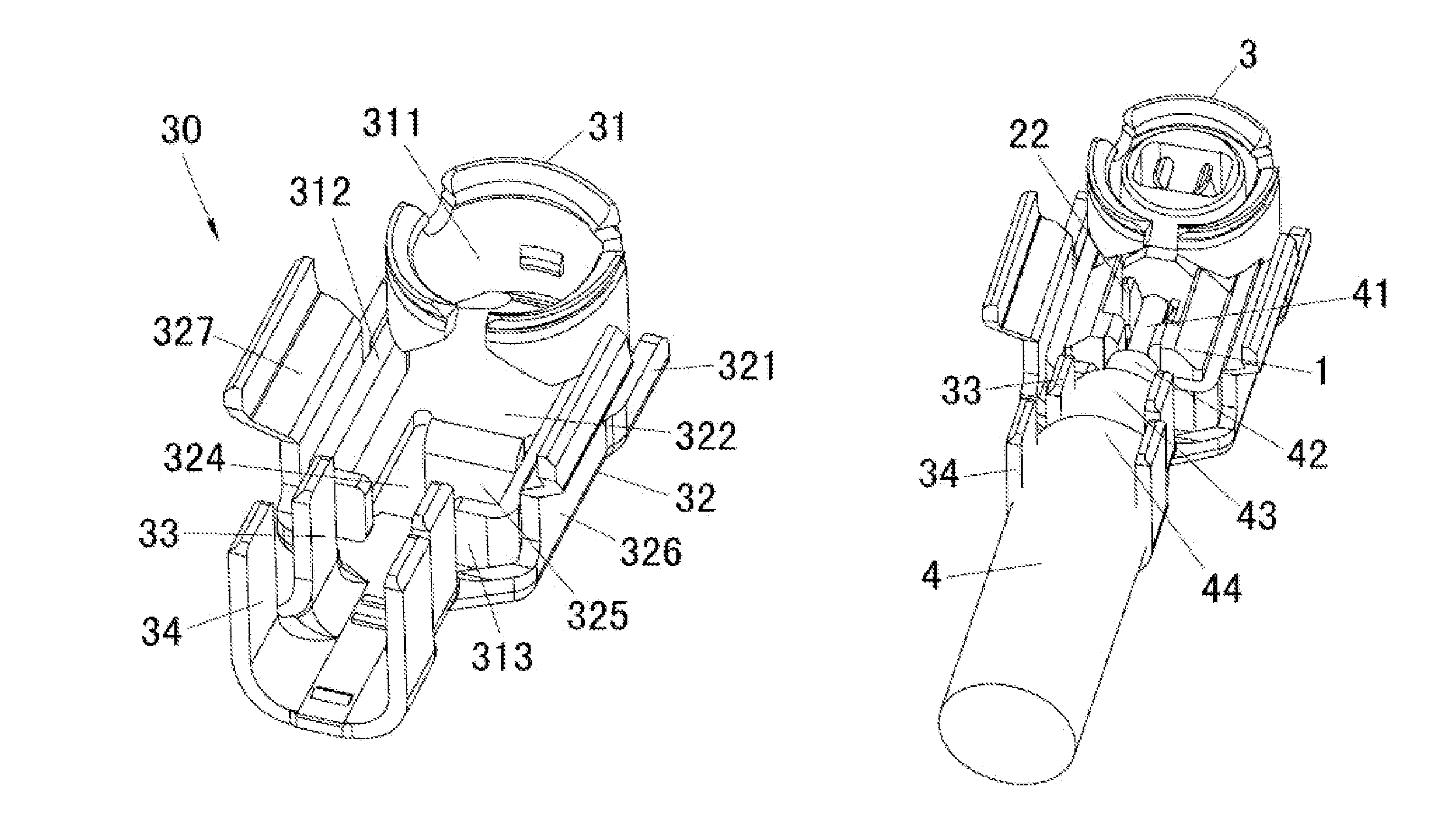
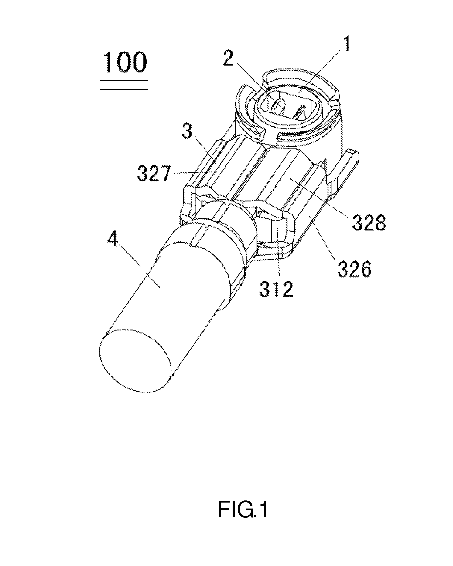
[0021]Please refer to FIG. 1, it is a one embodiment of the present invention. A coaxial connector includes an insulating housing 1, central terminals 2 received in the insulating housing 1, a shielding shell 3 covers the insulating housing 1 form outside, and a coaxial cable 4.

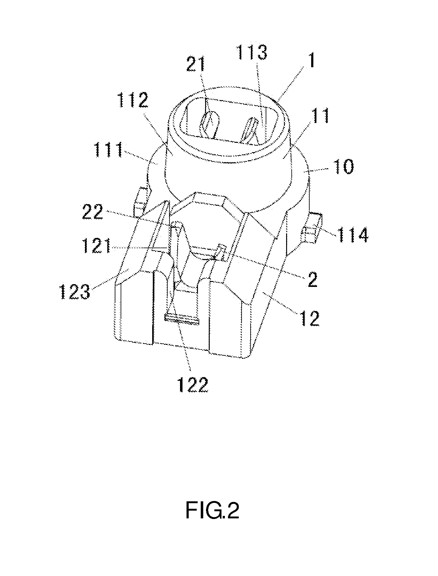
[0022]Please refer to FIG. 2, the insulating housing 1 and the central terminals 2 formed a docking assembly by insert molding, or it can be formed through assembly process, the insulating housing 1 comprise a cylinder portion 11 and a receptacle housing 12, the cylinder portion 11 comprises a base seat 111 and a hollow tubular shell 112 protruding upward form the base seat 111 and being concentric with the base seat, the hollow tubular shell 112 has a hollow portion 113 for receiving the contact 21 of the central terminal 2, the hollow portion 113 extends through the whole cylinder portion 11, two projecting portion 1...


PUM


Abstract

The present invention relates to a coaxial connector, more particularly relates to a coaxial connector with shielding shell that comprises a main body, a flat portion connected to the main body and a wire holder on the rear end of the flat portion. The main body includes a pair of holding arms and a receiving hole for receiving the cylinder portion of the insulating housing. The flat portion has a front end and a back end, the front end receives the cylinder portion and supports the main body after the main body being bent toward to the flat portion, and there is a cavity formed in the center of the back end through bending over a cover plate, the bending arms bend inward to cover the insulating housing and holding arms from outside.

Description

BACKGROUND OF THE INVENTION[0001]1. Field of the Invention[0002]The present invention relates to a coaxial connector, more particularly relates to a coaxial connector with shielding shell.[0003]2. Description of the Prior Art[0004]A coaxial connector is mainly used to connect cable and electron device for radio-frequency (RF) signal transmission, but it will cause interfering signal during transmission, so shielding shell play an important role to avoid the interference. Relevant existing technology, please refer to Chinese patent CN 01264762.4. Please refer to the figures of this patent, the figures show that the coaxial connector is composed of five parts, including an insulating housing 10, terminals 30 laying in the insulating housing, a shielding shell 50, a coaxial cable holding device 60 and a coaxial cable, the shielding shell 50 holds the insulating housing from outside, the holding device 60 holds the braid of the coaxial cable, and the holding device 60 be fixed to the sh...

Claims


Application Information

Patent Timeline
Patent Type & Authority Patents(United States)
IPC IPC(8): H01R9/05
CPCH01R9/0518H01R13/415H01R4/185H01R24/40H01R2103/00
Inventor CHEN, SHIH-CHIEH
Owner CHEN SHIH CHIEH
Why Eureka
Try Eureka