Assemblies and methods for clamping force generation

a technology of clamping force and assembly, applied in the direction of mechanical equipment, mechanical energy handling, gearing, etc., can solve the problems of difficulty in determining the proper clamping force generator for any given application, and difficulty in providing the adequate pre-load (or initial clamping force) necessary

Inactive Publication Date: 2012-11-27
FALLBROOK INTPROP COMPANY
View PDF431 Cites 89 Cited by
  • Summary
  • Abstract
  • Description
  • Claims
  • Application Information

AI Technical Summary

Problems solved by technology

However, devising the proper clamping force generator for any given application can be challenging.
For example, difficulties can arise in providing the adequate pre-load (or initial clamping force) necessary to avoid total traction loss and / or inefficiencies (due to lost motion, for example).

Method used


Image

  • Assemblies and methods for clamping force generation
  • Assemblies and methods for clamping force generation
  • Assemblies and methods for clamping force generation

Examples


Embodiment Construction

” one will understand how the features of the system and methods provide several advantages over traditional systems and methods.

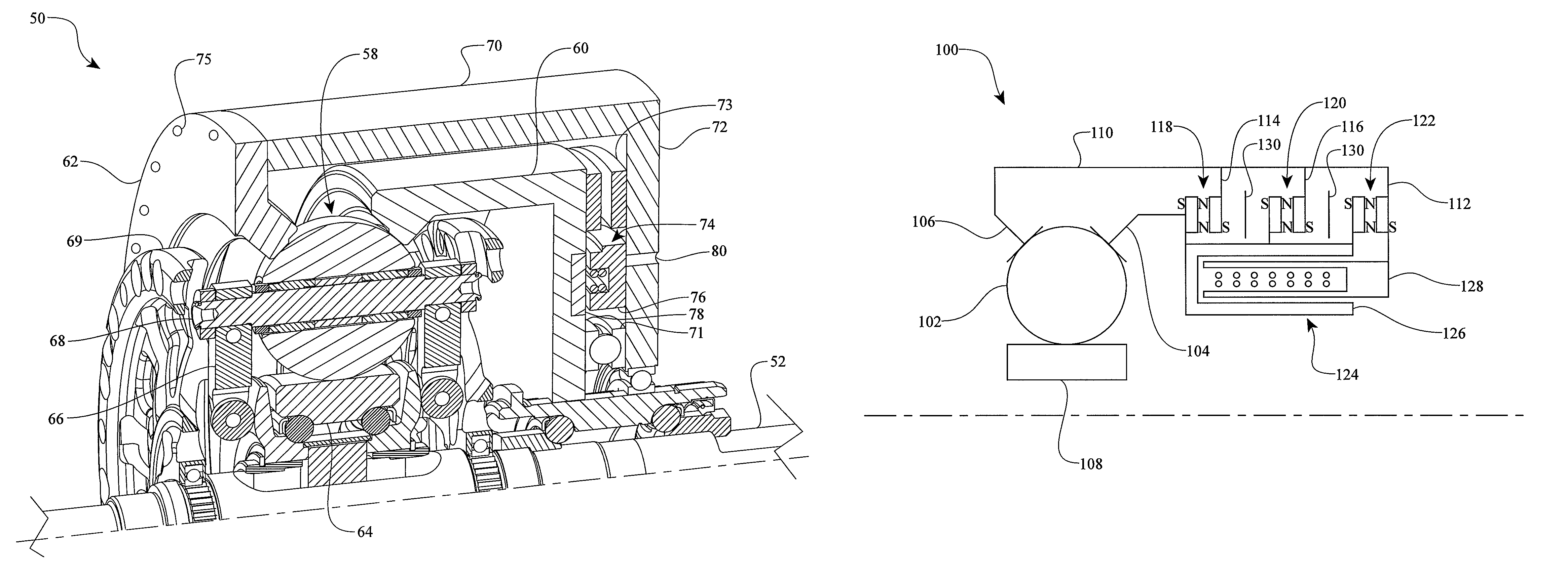
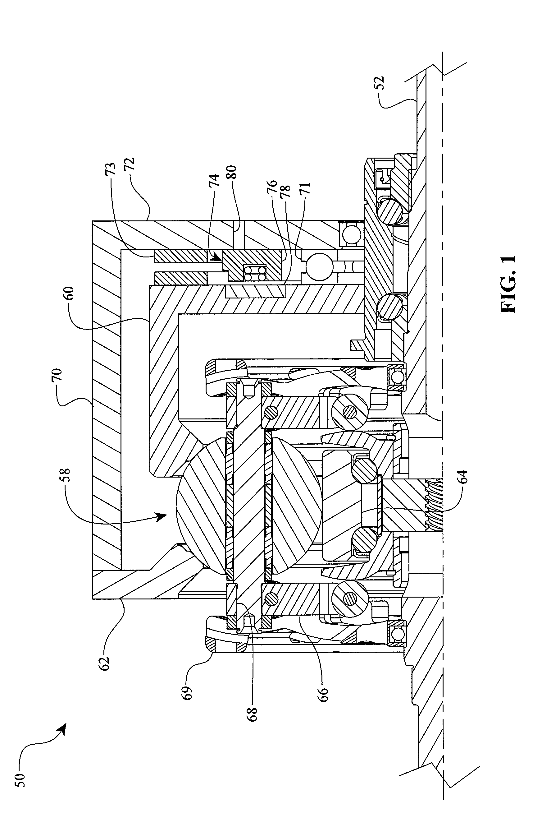
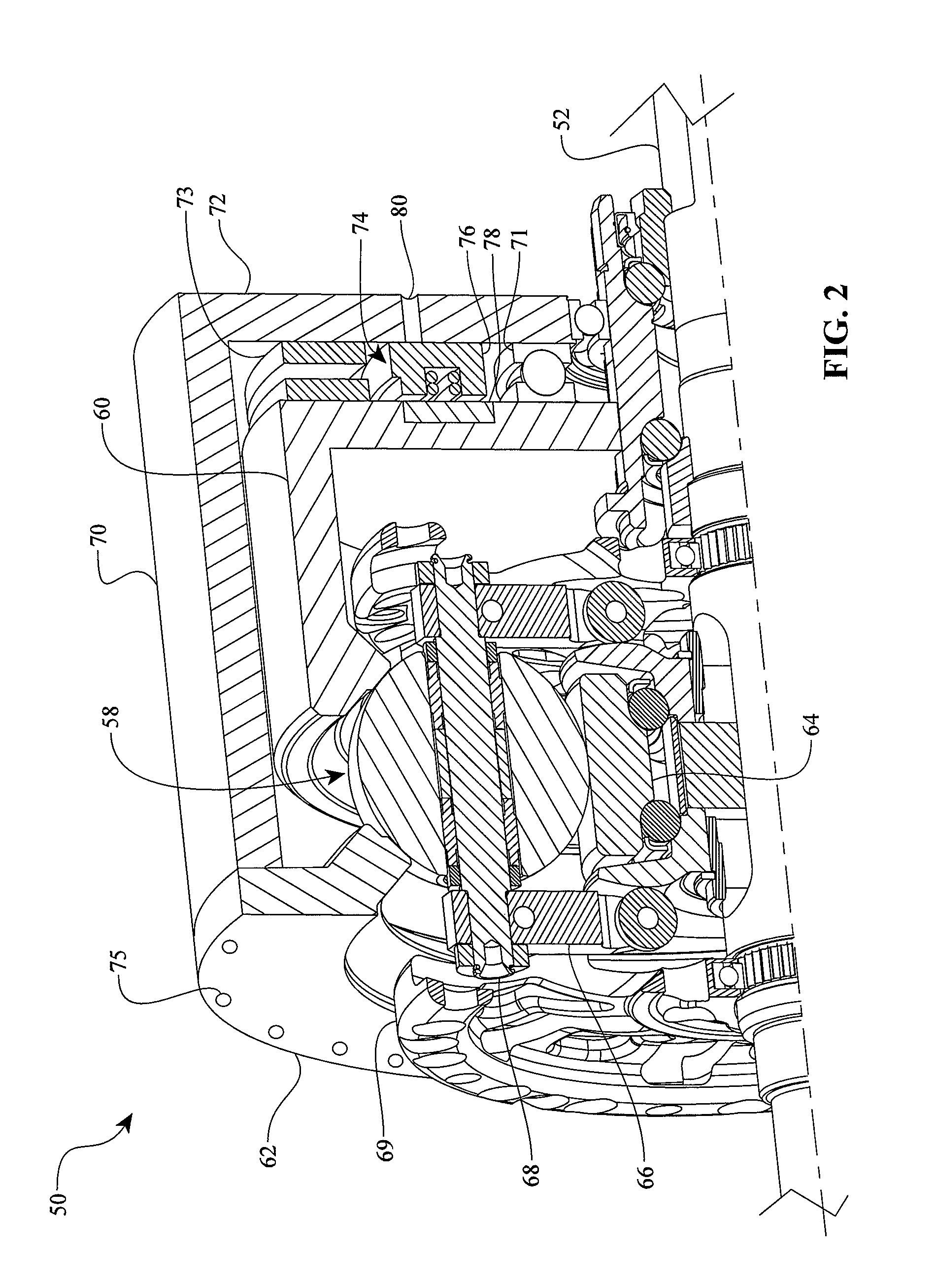
[0009]One aspect of the invention relates to a continuously variable transmission (CVT) having a group of spherical power rollers in contact with first and second traction rings and a support member. The CVT has a permanent magnet bearing coupled to the first traction ring. The permanent magnet bearing is coupled to the second traction ring. The CVT also has an electromagnetic bearing coupled to the first and second traction rings. The electromagnetic bearing is configured to generate an axial force between the power rollers, support member, and the first and second traction rings.

[0010]Another aspect of the invention concerns a method of controlling an axial force in a continuously variable transmission (CVT). The CVT has a group of spherical power rollers in contact with a first traction ring, a second traction ring, and a support member. The method incl...


PUM


Abstract

Mechanisms and methods for clamping force generation are disclosed. In one embodiment, a clamping force generator system includes a permanent magnet bearing coupled to a traction ring and to a torque coupling. The traction ring can be provided with an electromagnetic bearing rotor and the torque coupling can be provided with an electromagnetic bearing stator. In some embodiments, a mechanical load cam, a permanent magnet bearing, and an electromagnetic bearing cooperate to generate a clamping force between the traction rings, the power rollers, and the idler. In other embodiments, a series of permanent magnet bearings and a mechanical bearing configured to produce a clamping force. In one embodiment an electromagnetic bearing is coupled to a control system and produces a specified clamping force that is associated with a torque transmitted in the transmission during operation. In some embodiments, a mechanical load cam produces a clamping force proportional to torque, while a permanent magnet bearing provides a minimum clamping force.

Description

CROSS REFERENCE TO RELATED APPLICATIONS[0001]This application claims the benefit of U.S. Provisional Patent Application No. 61 / 051,248, filed on May 7, 2008, which is hereby incorporated by reference in its entirety.BACKGROUND OF THE INVENTION[0002]1. Field of the Invention[0003]The field of the invention relates generally to mechanical power transmissions, and more particularly the invention pertains to devices and methods relating to generating clamping force in certain types of said transmissions.[0004]2. Description of the Related Art[0005]Certain transmissions, for example some continuously or infinitely variable transmissions, often include one or more mechanisms for generating a clamping force that facilitates the transmission of torque between or among transmission components via traction or friction. Some clamping force generators are referred to as axial force generators (AFGs) because, typically, the clamping force produced by the AFGs resolves (or must be reacted) along ...

Claims


Application Information

Patent Timeline
Patent Type & Authority Patents(United States)
IPC IPC(8): F16H15/38
CPCF16H15/52F16H15/503F16H15/50F16H59/14F16H59/38F16H61/6645F16H61/6649F16H63/304
Inventor LOHR, CHARLES B.
Owner FALLBROOK INTPROP COMPANY
Why Eureka
Try Eureka