
Post-beamforming compression in ultrasound systems

a compression and ultrasound technology, applied in the field of compression of beamformed samples, can solve the problems of reducing the storage capacity needed in the mass memory device, yaegashi does not disclose the beamforming in the processing sequence, and compression may be lossless or lossy, so as to reduce the storage capacity required for storing compressed beamformed samples, computationally efficient compression and decompression

Inactive Publication Date: 2012-11-27
ALTERA CORP
View PDF16 Cites 10 Cited by
  • Summary
  • Abstract
  • Description
  • Claims
  • Application Information

AI Technical Summary

Benefits of technology

[0023]Another advantage of the present invention includes efficient storage of the compressed beamformed samples. For a system architecture where the beamformed samples are stored in a memory or other storage media, the storage capacity required for storing the compressed beamformed samples is reduced compared to uncompressed beamformed samples.
[0024]Another advantage of the present invention includes computationally efficient compression and decompression. The implementations of compression and decompression are less complex, reducing the burden on system resources and reducing the cost. Other aspects and advantages of the present invention can be seen on review of the drawings, the detailed description and the claims, which follow.

Problems solved by technology

The data compression reduces the storage capacity needed in the mass memory device.
Yaegashi does not disclose beamforming in the processing sequence.
The compression may be lossless or lossy.
A variable number of least significant bits are removed from each sample, so the compression is lossy.

Method used


Image

  • Post-beamforming compression in ultrasound systems
  • Post-beamforming compression in ultrasound systems
  • Post-beamforming compression in ultrasound systems

Examples


Embodiment Construction

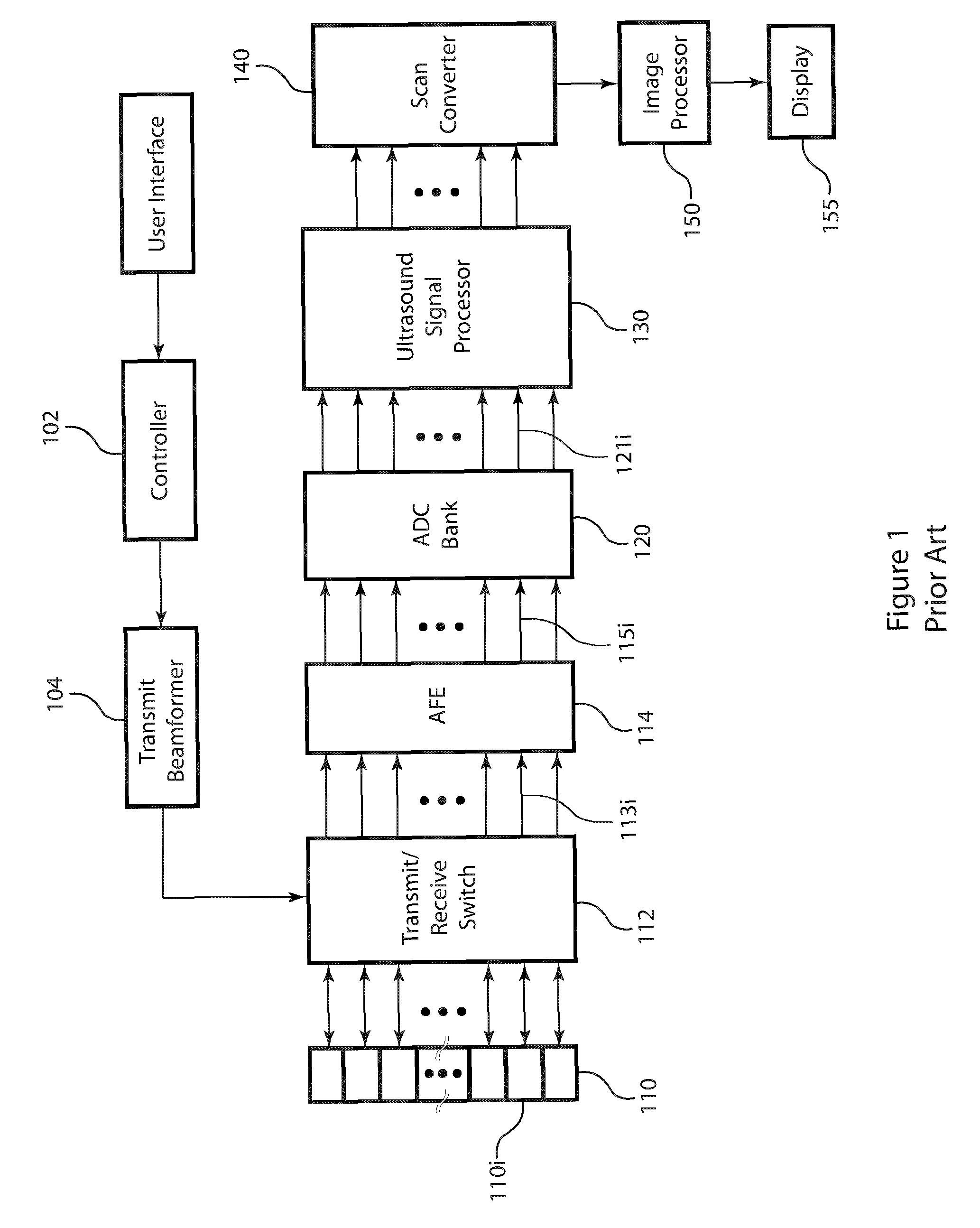
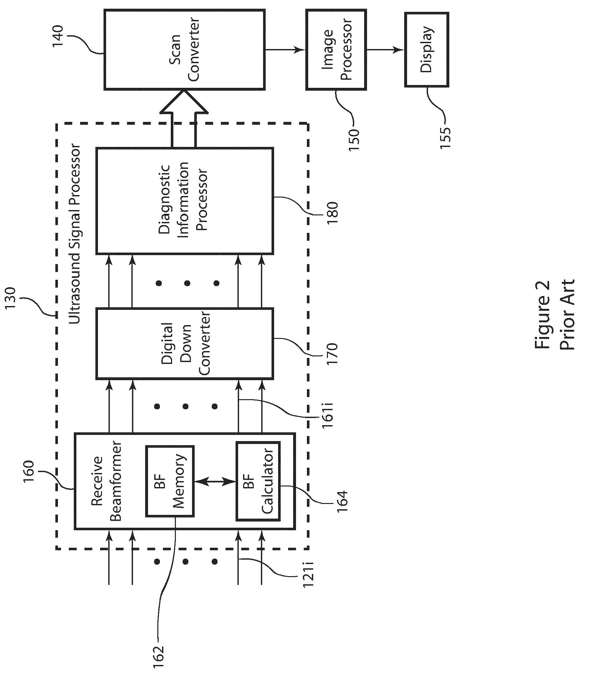
[0049]FIG. 1 is a block diagram of an example of a typical medical ultrasound system in accordance with the prior art. The transmit beamformer 104 is of a construction known in the art, such as a digital or analog beamformer. The transmit beamformer 104 generates one or more excitation signals in response to the system controller 102. The excitation signal has an associated center frequency, typically in the 1 to 20 MHz range. The excitation signals from the transmit beamformer 104 are provided to the ultrasound transducer 110 via the transmit / receive switch 112. The ultrasound transducer 110 comprises an array of transducer elements 110i. The ultrasound transducer 110 is of a construction known in the art that enables the coupling the ultrasound waves to the subject being examined. The transducer elements 110i both launch and receive ultrasound waves. The transmit / receive switch 112 includes the switching circuitry for transmit and receive modes. For transmit mode, the transmit / rec...


PUM


Abstract

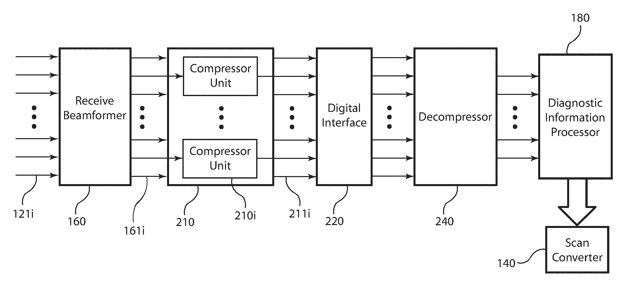
In an ultrasound imaging system that applies a beamformer to received ultrasound signal samples to form one or more beams represented by arrays of beamformed samples, a method and an apparatus compress each array of beamformed samples independently of the other arrays to form compressed beams. A plurality of analog to digital converters sample multiple analog ultrasound signals produced by a transducer array to provide multiple streams of ultrasound signal samples to the beamformer. The compressed beams are transferred via a digital interface to a signal processor. At the signal processor, the compressed beams are decompressed to form decompressed beams. The signal processor further processes the decompressed beams for diagnostic imaging, such as for B-mode and Doppler imaging, and scan conversion to prepare the resulting ultrasound image for display. This abstract does not limit the scope of the invention as described in the claims.

Description

BACKGROUND OF THE INVENTION[0001]The present invention relates to compression of beamformed samples produced in an ultrasound imaging system by a receive beamformer applied to received ultrasound signal samples, particularly to compressing the beamformed samples of each beam independently and decompressing prior to processing for image formation.[0002]Medical ultrasound systems scan the internal anatomy of a subject by transmitting ultrasound beams from a transducer placed on the subject by a clinician. The ultrasound waves are reflected at interfaces of internal tissues having different acoustic impedances, producing echoes. The transducer receives the echoes and converts them to electrical ultrasound signals. The ultrasound system applies a sequence of processing steps to the ultrasound signals to produce an image or series of images that are displayed at a control console for analysis by the clinician. Images formed based on the strength of the received echo are referred to as B-...

Claims


Application Information

Patent Timeline
Patent Type & Authority Patents(United States)
IPC IPC(8): A61B8/00
CPCA61B8/06A61B8/13A61B8/488A61B8/54G01S7/52034G01S7/52023G10K11/346H03M7/40
Inventor WEGENER, ALBERT W.
Owner ALTERA CORP
Learn More