Multi-port RF systems and methods for MRI

a multi-port, rf technology, applied in the field of magnetic resonance imaging, can solve the problems of rf loss in the object, dictate rf power deposition/noise, contribute to the noise in the received time signal data,

Active Publication Date: 2012-11-27
ZHU YUDONG
View PDF9 Cites 20 Cited by
  • Summary
  • Abstract
  • Description
  • Claims
  • Application Information

AI Technical Summary

Problems solved by technology

The concomitant E field meanwhile gives rise to RF loss in the object and dictates RF power deposition / noise.
The RF loss associated with the concomitant E field in this case contributes to the noise in the received time signal data.
However, there has not been a viable method that, under in vivo conditions, effectively taps into this capacity and realizes imaging performance enhancement with SAR reduction.
In fact the substantially increased degrees of freedom inherent of parallel transmit, which are the very foundation of this capacity, tend to spur a concern that improper RF pulse or shimming calculations, or multi-channel hardware failure, may inadvertently exacerbate SAR, as opposed to reducing it.

Method used


Image

  • Multi-port RF systems and methods for MRI
  • Multi-port RF systems and methods for MRI
  • Multi-port RF systems and methods for MRI

Examples


Embodiment Construction

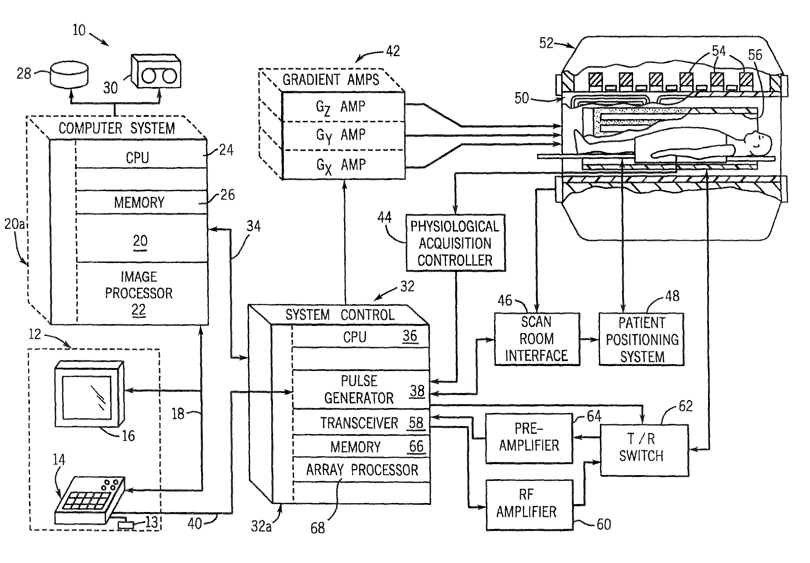
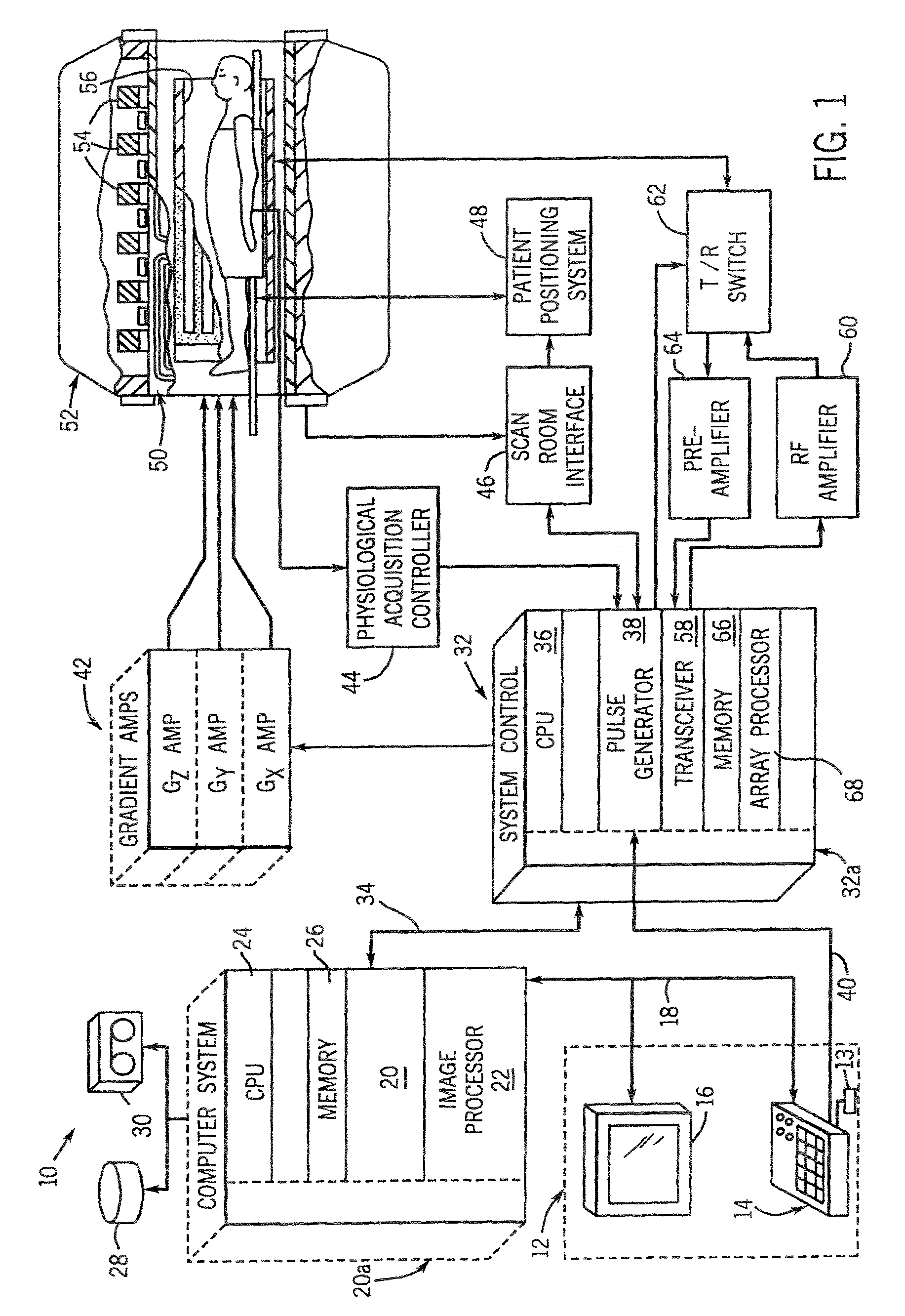
[0017]Referring to FIG. 1, the major components of a preferred magnetic resonance (MR) system 10 incorporating the present invention are shown. The operation of the system is controlled from an operator console 12 which includes a keyboard or other input device 13, a control panel 14, and a display screen 16. The console 12 communicates through a link 18 with a separate computer system 20 that enables an operator to control the production and display of images on the display screen 16. The computer system 20 includes a number of modules which communicate with each other through a backplane 20a. These include an image processor module 22, a CPU module 24 and a memory module 26, known in the art as a frame buffer for storing image data arrays. The computer system 20 is linked to disk storage 28 and tape drive 30 for storage of image data and programs, and communicates with a separate system control 32 through a high speed serial link 34.

[0018]The system control 32 includes a set of mo...


PUM


Abstract

Optimizing RF coil currents' magnitude / phase relationship, temporal modulation and spatial distribution is crucial to MR imaging performance. One key aspect for the optimization is the knowledge of B1 spatial distribution and RF power deposition associated with a coil current pattern or a source configuration, and the use of the knowledge in the optimization. Another key aspect for the optimization is a hardware infrastructure that facilitates the optimization, with, specifically, a coil structure that supports flexible current path control. The present invention relates to calibration methods and multi-channel parallel RF transmit / receive coil assemblies that improve the performance of MR imaging by addressing both aspects.

Description

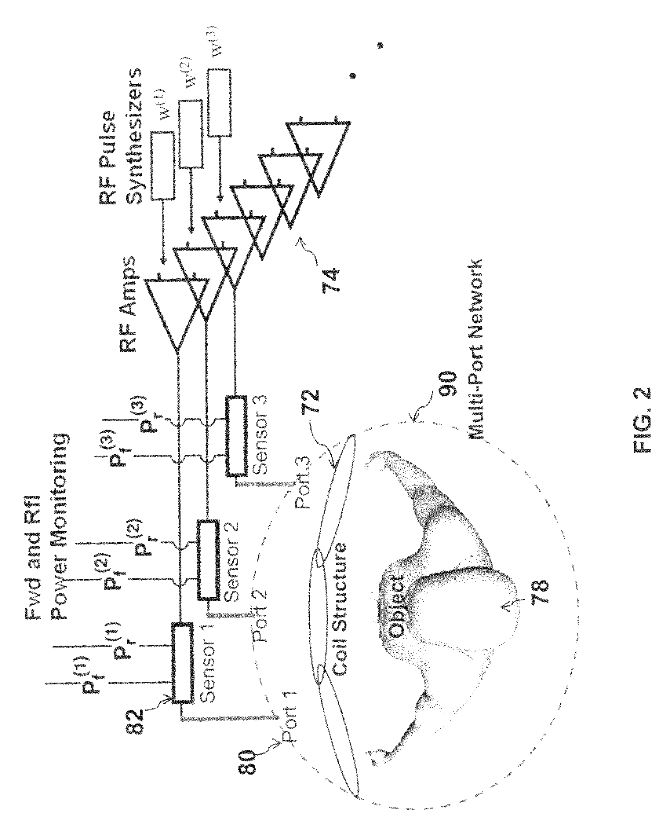
[0001]This application claims the benefit of PPA Application No. 61 / 108,554 filed 2008 Oct. 27 by the present inventor, which is incorporated by reference.BACKGROUND OF THE INVENTION[0002]The present invention relates generally to magnetic resonance (MR) imaging and, more particularly, to multi-channel or multi-port parallel RF transmit (Tx) / receive (Rx). The present invention further relates to a calibration method and a multi-channel parallel RF transmit / receive coil assembly that improve the performance of MR imaging.[0003]When radio-frequency signal gets transmitted / detected during MR imaging, it is the B1+ / B1− fields in the object, not the driving / induced currents in the RF coil structure, that interact directly with the spin system (nuclei) of an imaged object. The concomitant E field meanwhile gives rise to RF loss in the object and dictates RF power deposition / noise. Yet the coil currents play a central role—they act as the link between Tx / Rx system electronics and the RF el...

Claims


Application Information

Patent Timeline
Patent Type & Authority Patents(United States)
IPC IPC(8): G01V3/00
CPCG01R33/5612G01R33/34007
Inventor ZHU, YUDONG
Owner ZHU YUDONG
Why Eureka
Try Eureka