Lamp source module and projection system

a technology of source module and projection system, which is applied in the direction of projectors, lighting and heating equipment, instruments, etc., can solve the problems of reducing cooling effect, affecting the effect of lighting effect, so as to prevent explosions, good shading, and good cooling

Active Publication Date: 2012-12-04
YOUNG GREEN ENERGY
View PDF20 Cites 9 Cited by
  • Summary
  • Abstract
  • Description
  • Claims
  • Application Information

AI Technical Summary

Benefits of technology

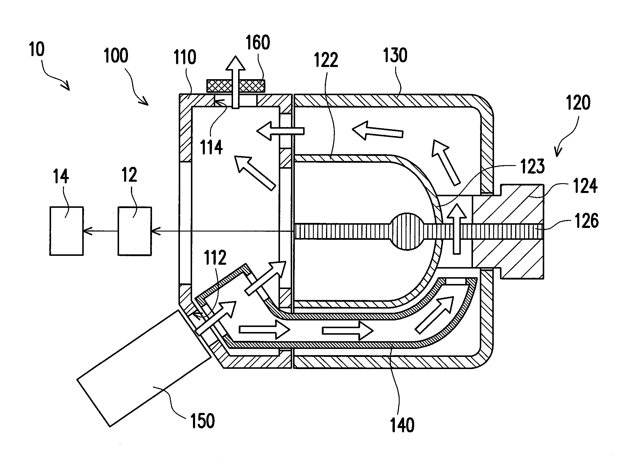
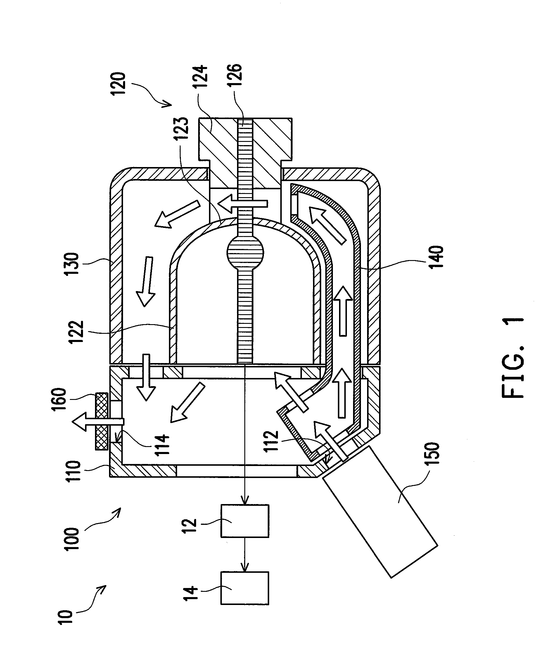
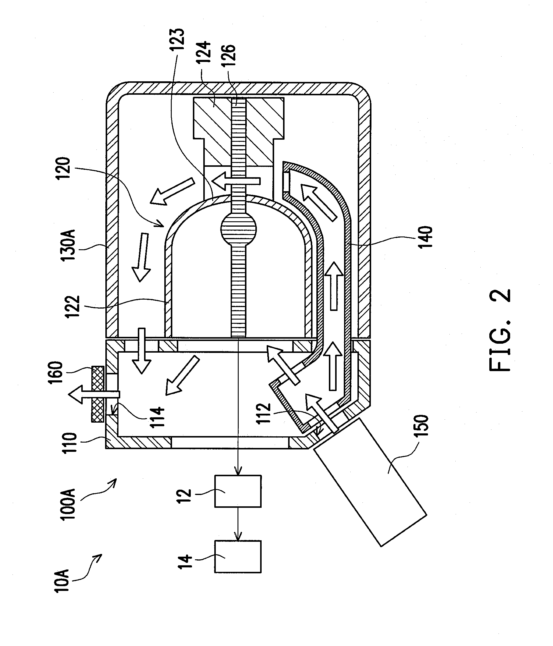
[0009]The invention provides a lamp source module having good shading, explosion prevention, and cooling effects.
[0010]The invention provides a projection system having a lamp source module with good shading, explosion prevention, and cooling effects.
[0014]Based on the embodiment of the invention, part of the burner inside the bottom of the lamp reflector is cooled by the cooling airflow directed from the airflow generator to the bottom of the lamp reflector via the blower duct. Therefore, openings for the cooling airflow to enter and exit may not be formed by the light cover so a completely enclosed structure is provided to effectively eliminate light leakage from the lamp reflector and also improve explosion prevention ability.

Problems solved by technology

However, the bulb of the ultra high pressure mercury lamp under improper use may explode and cause the lamp reflector for reflecting light to break and the broken pieces of the lamp reflector may be spattered outside the light cover through the ventilation openings.
However, such design causes decreased cooling effects and increased part costs.

Method used


Image

  • Lamp source module and projection system
  • Lamp source module and projection system
  • Lamp source module and projection system

Examples


Embodiment Construction

[0021]In the following detailed description of the preferred embodiments, reference is made to the accompanying drawings which form a part hereof, and in which are shown by way of illustration specific embodiments in which the invention may be practiced. In this regard, directional terminology, such as “top,”“bottom,”“front,”“back,” etc., is used with reference to the orientation of the Figure(s) being described. The components of the invention can be positioned in a number of different orientations. As such, the directional terminology is used for purposes of illustration and is in no way limiting. On the other hand, the drawings are only schematic and the sizes of components may be exaggerated for clarity. It is to be understood that other embodiments may be utilized and structural changes may be made without departing from the scope of the invention. Also, it is to be understood that the phraseology and terminology used herein are for the purpose of description and should not be ...


PUM


Abstract

A lamp source module includes a holder having an air inlet and an air outlet, a gas discharge lamp having a lamp reflector assembled onto the holder and a burner disposed in the lamp reflector, a light cover assembled on the holder and surrounding the lamp reflector, a blower duct communicating with the air inlet and extending along the exterior of the lamp reflector to the bottom of the lamp reflector, and an airflow generator communicating with the blower duct and capable of providing a cooling airflow. The air inlet is capable of causing the cooling airflow to enter the blower duct. The blower duct is capable of directing the cooling airflow to the bottom of the lamp reflector to make the cooling airflow pass through a sandwiched space surrounded by the lamp reflector and the light cover and then discharge from the air outlet.

Description

CROSS-REFERENCE TO RELATED APPLICATION[0001]This application claims the priority benefit of China application serial no. 200910166001.2, filed on Aug. 7, 2009. The entirety of the above-mentioned patent application is hereby incorporated by reference herein and made a part of this specification.BACKGROUND OF THE INVENTION[0002]1. Field of the Invention[0003]The invention relates to a lamp source module and more particularly, to a lamp source module adapted to a projection system.[0004]2. Description of Related Art[0005]Most of the current lamp source modules of projectors adopt ultra high pressure mercury lamps, and the ultra high pressure mercury lamps are a type of gas discharge lamps. To avoid light leakage, the lamp source module further includes a light cover covering the lamp base of the lamp source module from the back of the lamp.[0006]Due to the extremely high operating temperature of the ultra high pressure mercury lamp, cooling the burner of the lamp in operation is requi...

Claims


Application Information

Patent Timeline
Patent Type & Authority Patents(United States)
IPC IPC(8): G03B21/18
CPCF21V29/02G03B21/16G03B21/2026G03B21/2086F21V29/67F21V29/60
Inventor TSAI, TE-YINGWU, SHANG-HSUANGCHOU, CHIH-CHENGLIAO, YI-KUAN
Owner YOUNG GREEN ENERGY
Why Eureka
Try Eureka