Lighting assemblies having controlled directional heat transfer

a technology of directional heat transfer and light assembly, which is applied in the direction of lighting and heating equipment, semiconductor devices for light sources, and power sources with built-in, can solve the problems of leds failing prematurely, shortening the life of leds, and affecting the implementation of led-based lighting systems. the effect of heat transfer

Active Publication Date: 2012-12-04
EATON INTELLIGENT POWER LTD
View PDF47 Cites 22 Cited by
  • Summary
  • Abstract
  • Description
  • Claims
  • Application Information

AI Technical Summary

Benefits of technology

[0005]The present invention satisfies the above-described need by providing a LED-based lighting system having capabilities for controlled heat transfer from a light source assembly to an exterior of a lighting fixture, while minimizing transfer of heat to components within a driver housing.
[0006]In one aspect, a lighting fixture having controlled directional heat transfer can include a light source assembly, a heat sink, a conductive sealing member, such as a thermal gasket, positioned between the heat sink and the light source assembly, and a driver housing for containing components for controlling the lighting fixture. The conductive sealing member generally has a thermal conductivity of at least about 6 Watts per meter-Kelvin (W / mK), and / or a thermal impedance of less than about 0.21 degree-C. inch squared per Watt (° C.-in2 / W). The light source assembly can include an array of LEDs. The heat sink can include fins extending from a central housing of the heat sink. A nonconductive or semi-conductive sealing member, such as a silicone gasket, can be positioned between the heat sink and the driver housing so as to minimize the amount of heat transferred from the heat sink to the driver housing. Alternatively, a conduit can be to the driver housing and the heat sink to provide a gap between the driver housing and the heat sink. The conduit provides a passageway from an interior of the heat sink to an interior of the driver housing. The driver housing can be positioned at a location remote from the light source assembly and the heat sink, and be electrically coupled to the light source assembly by wiring.

Problems solved by technology

However, the implementation of LED-based lighting systems has been hindered by the amount of heat build-up within the lighting assembly.
Heat build-up within the lighting assembly can reduce light output of the LEDs and shorten the lifespan of the LEDs, thus potentially causing the LEDs to fail prematurely.
However, conventional LED-based lighting systems employing heat sinks typically have poor heat transfer between the LEDs and the heat sink, and / or the heat drawn away from the LEDs is transferred to other heat sensitive components, such as drivers in the assembly.

Method used


Image

  • Lighting assemblies having controlled directional heat transfer
  • Lighting assemblies having controlled directional heat transfer
  • Lighting assemblies having controlled directional heat transfer

Examples


example 1

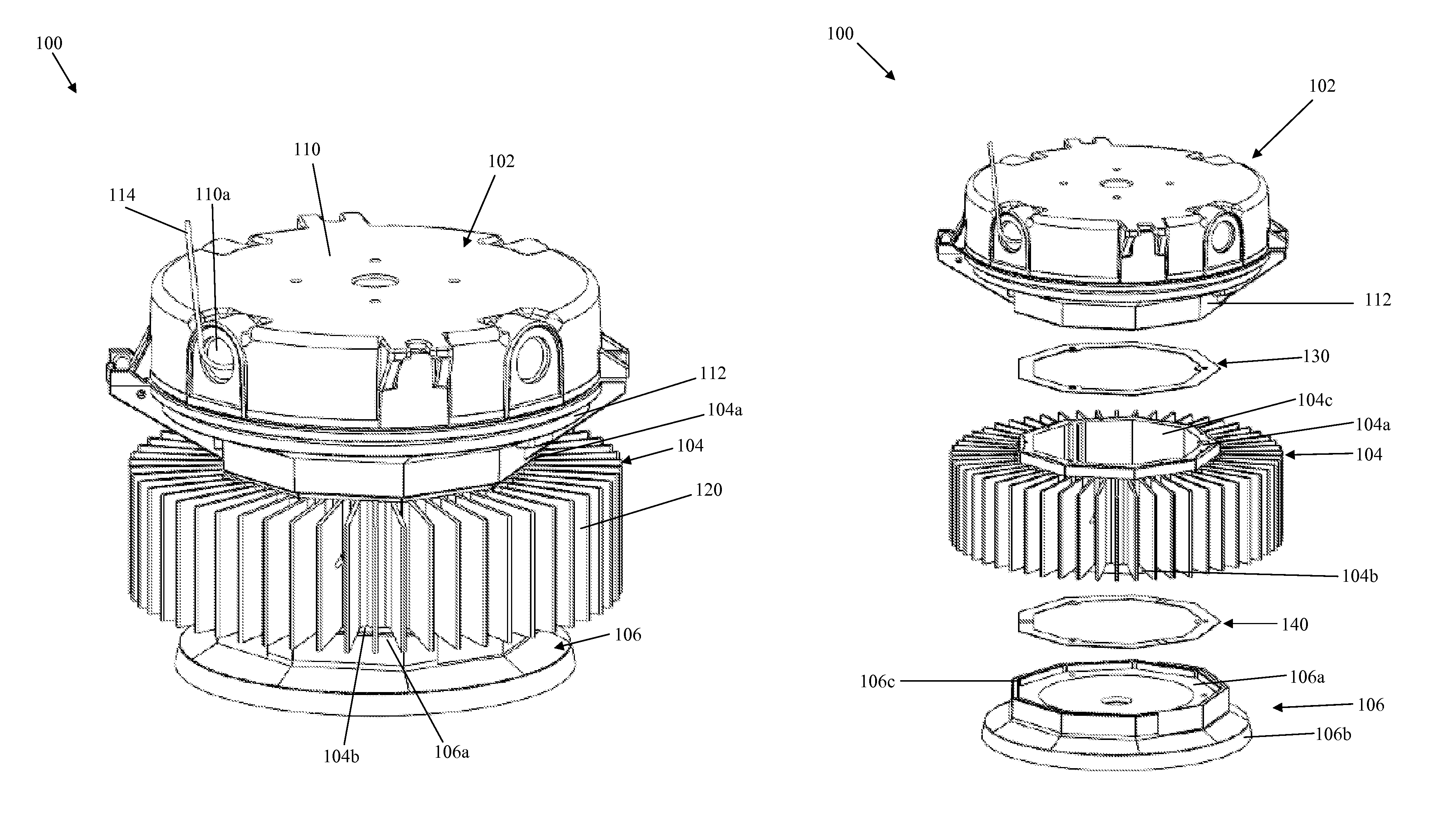
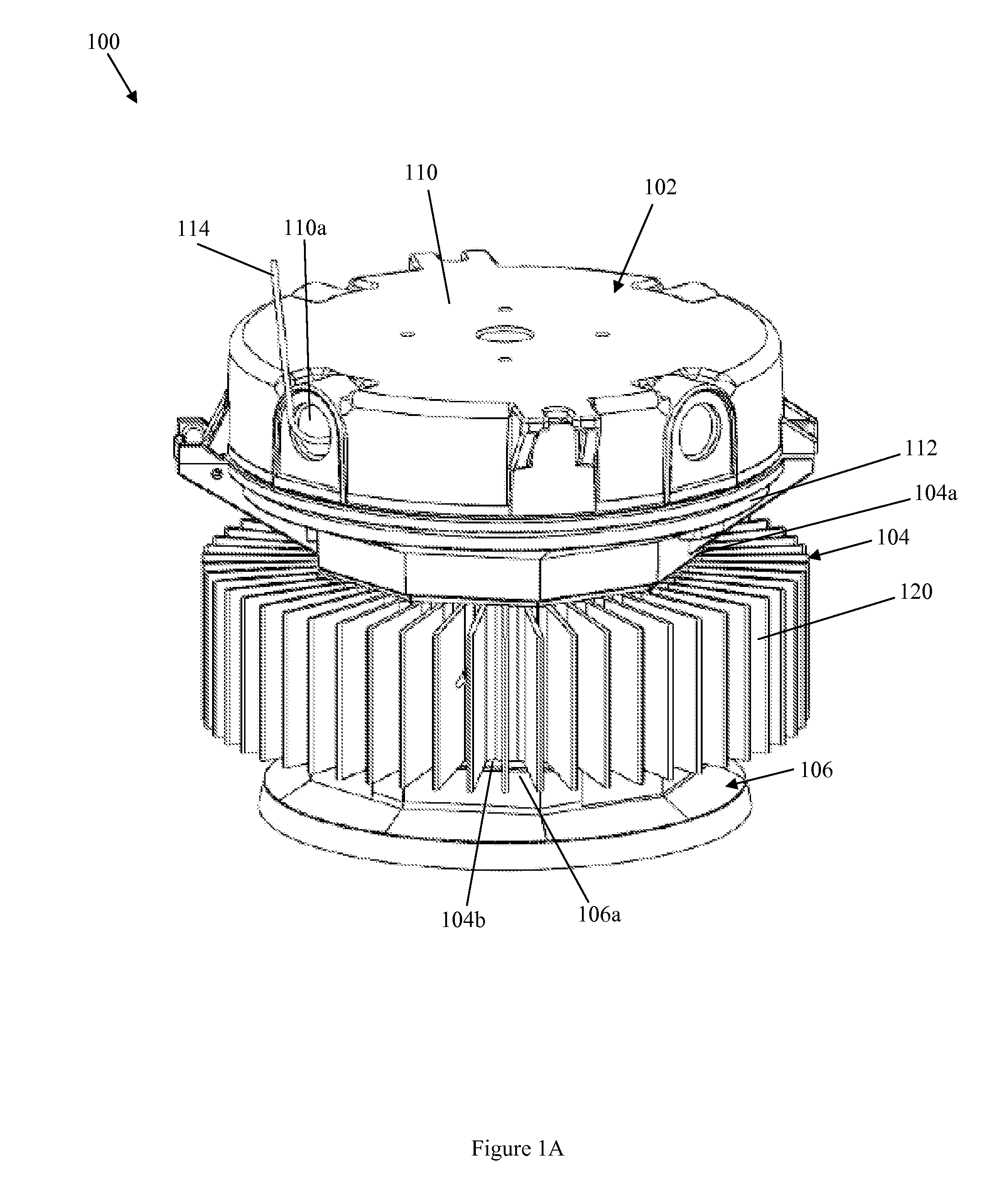
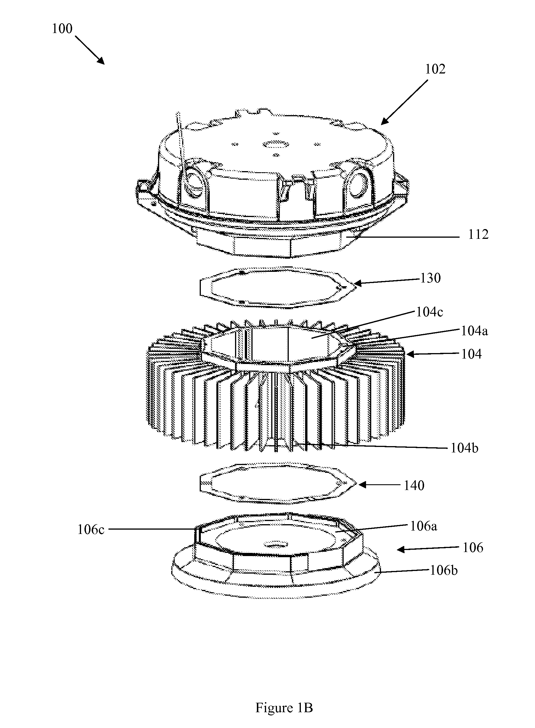
[0030]A lighting fixture of the present invention was subjected to Cycling Rain and Dielectric Withstand testing per UL1598 section 16.5.2 and 17.1 (dated Sep. 17, 2008). The lighting fixture included a thermal gasket positioned between a heat sink and a LED assembly, and a silicone gasket positioned between a driver housing and the heat sink, as shown and described with respect to FIGS. 1A-1C. The thermal gasket had a thermal conductivity of 6 W / mK and a thermal impedance of 0.21° C.-in2 / W. The silicone gasket had a thermal conductivity of 0.22 W / mK. The lighting fixture included two LED drivers (EWC-050S119SS-0021, 50W, input voltage / current 100-240 VAC / 0.7 A, 50 / 60 Hz, output voltage / current 21-42 VDC / 1.19 A, UL, CSA, CE, IP67) commercially available from Inventronics, six LED arrays (BXRA-C1200, cool white) commercially available from Bridgelux, and a pendant mount cover (catalog number PM2) commercially available from Cooper Crouse-Hinds.

[0031]The interior of the lighting fixtu...

example 2

[0033]The environmental sealing effect of the presence of a thermal gasket in a lighting fixture of the present invention was tested. A lighting fixture including a thermal gasket positioned between a heat sink and a LED assembly, and a silicone gasket positioned between a driver housing and the heat sink, as shown and described with respect to FIGS. 1A-1C, was subjected to Marine Hose testing per UL1598A section 16 (dated Jun. 17, 2005). The thermal gasket had a thermal conductivity of 6 W / mK and a thermal impedance of 0.21° C.-in2 / W. The silicone gasket had a thermal conductivity of 0.22 W / mK. The lighting fixture included two LED drivers (EWC-050S119SS-0021, 50W, input voltage / current 100-240 VAC / 0.7 A, 50 / 60 Hz, output voltage / current 21-42 VDC / 1.19 A, UL, CSA, CE, IP67) commercially available from Inventronics, six LED arrays (BXRA-C1200, cool white) commercially available from Bridgelux, and a pendant mount cover (catalog number PM2) commercially available from Cooper Crouse-H...

example 3

[0036]Temperature tests were performed on a lighting fixture to determine the temperature differences of the fixture components using (i) no gasket, (ii) a silicone gasket, and (iii) a thermal gasket positioned between a heat sink and a LED assembly of the lighting fixture. Each of the lighting fixtures included two LED drivers (EWC-050S119SS-0021, 50W, input voltage / current 100-240 VAC / 0.7 A, 50 / 60 Hz, output voltage / current 21-42 VDC / 1.19 A, UL, CSA, CE, IP67) commercially available from Inventronics, six LED arrays (BXRA-C1200, cool white) commercially available from Bridgelux, and a ceiling mount cover (catalog number CM2) commercially available from Cooper Crouse-Hinds.

[0037]A lighting fixture having a thermal gasket, series 220 MS2423 commercially available from Thermagon, between the heat sink and the LED assembly was mounted in a room with provisions for maintaining a constant ambient temperature. The thermal gasket had a thermal conductivity of 6 W / mK and a thermal impedanc...


PUM


Abstract

Lighting assemblies or lighting fixtures suitable for use in a hazardous location are provided. Generally, the lighting fixtures include a light source assembly, a heat sink, a driver housing or gear module, and a conductive sealing member between the light source assembly and the heat sink. The conductive sealing member has a thermal conductivity of at least about 6 Watts per meter-Kelvin, and / or a thermal impedance of less than about 0.21 degree-C. inch squared per Watt. The lighting fixtures have controlled directional heat transfer from the light source assembly to the exterior of the lighting fixture, while minimizing the heat transferred to the driver housing.

Description

TECHNICAL FIELD[0001]The application relates generally to light-emitting diode (LED)-based technology lighting systems, and more particularly, to lighting assemblies or lighting fixtures having controlled directional heat transfer.BACKGROUND OF THE INVENTION[0002]Lighting systems utilizing LEDs are widely used in various applications including, but not limited to, hazardous area lighting, general indoor and outdoor lighting, and backlighting. Lighting systems utilizing LEDs are a longer lasting, more efficient alternative to using lighting systems utilizing conventional light sources such as incandescent lamps and fluorescent light sources. However, the implementation of LED-based lighting systems has been hindered by the amount of heat build-up within the lighting assembly. Heat build-up within the lighting assembly can reduce light output of the LEDs and shorten the lifespan of the LEDs, thus potentially causing the LEDs to fail prematurely.[0003]Heat sinks are typically used in L...

Claims


Application Information

Patent Timeline
Patent Type & Authority Patents(United States)
IPC IPC(8): F21V29/00
CPCF21V29/004F21V31/005F21V25/12F21V29/773F21V15/01F21V23/008F21V29/15F21V29/75F21Y2101/02F21S9/022F21Y2115/10F21V29/00F21V31/00F21V29/767
Inventor BLINCOE, PATRICK STEPHENLITTEER, ANDREW ADAMS
Owner EATON INTELLIGENT POWER LTD
Why Eureka
Try Eureka