Modular LED lamp and manufacturing methods

a technology of led lamps and manufacturing methods, applied in the direction of printed circuit assembling, light support devices, gas-filled discharge tubes, etc., can solve the problems of not being able to simply dispose of spent lamps at the curbside, the resistance of switching to alternative light sources, and the inability to adopt newer technologies widely, so as to facilitate volume manufacturing and eliminate hand wiring

Inactive Publication Date: 2012-12-04
KORRUS INC
View PDF39 Cites 38 Cited by
  • Summary
  • Abstract
  • Description
  • Claims
  • Application Information

AI Technical Summary

Benefits of technology

[0010]This invention provides a high efficiency lighting sources with increased light output, without increasing device costs or size, yet enables coverage of many beam angles, with high reliability and long life. Embodiments of the invention include an MR16 form factor light source. A lighting module includes from 20 to 110 LEDs arrayed in series upon a thermally conductive substrate. The substrate is soldered to a flexible printed circuit substrate (FPC) having a pair of input power connectors. The silicon substrate is physically bonded to an MR16 form factor heat sink via thermal epoxy. A driving module includes a high-temperature operating driving circuit attached to a rigid printed circuit board or a flexible printed circuit substrate. The driving circuit and FPC are encased in a thermally conductive plug base that is compatible with an MR16 plug, forming the base assembly module. A potting compound facilitating heat transfer from the driving circuit to the thermally conductive plug case is typically used. The driving circuits are coupled to input power contacts (e.g. 12, 24, 120, 220 volt AC) and coupled to output power connectors (e.g. 40 VAC, 120 VAC, etc.) The base assembly module is inserted into and secured within an interior channel of the MR16 form factor heat sink. The input power connectors are coupled to the output power connectors. A lens is then secured to the heat sink.
[0012]The MR16 form factor heat sink facilitates the dissipation of heat. The heat sink includes an inner core that has a diameter less than half the outer diameter of the heat sink, and can be less than one third to one fifth the outer diameter. The silicon substrate of the LEDs is directly bonded to the inner core region with thermal epoxy.
[0017]In another aspect of the invention, an illumination source includes an MR-16 compatible heat sink coupled to an LED assembly. The MR-16 compatible heat sink has an inner core region and an outer core region, with the LED assembly disposed in the inner core region. The simplified construction facilitates volume manufacturing, elimination of hand wiring

Problems solved by technology

Despite the availability and improved efficiencies of these options, many people are reluctant to switch to these alternative light sources.
The newer technologies have not been widely embraced for various reasons.
Because the mercury vapor is a hazardous material, spent lamps cannot simply be disposed of at the curbside, but must be transported to designated hazardous waste disposal sites.
Another reason for the slow adoption of alternative lighting sources is its low performance compared to the incandescent light bulb.
In addition fluorescent lights typically do not immediately provide light at full brightness, instead ramping up to full brightness over time.
Further, most fluorescent lights are fragile, are not capable of dimming, have ballast transformers that can be noisy, and can fail if cycled on and off frequently.
LED lighting sources, however, have drawbacks that cause consumers to be reluctant to use them.
One disadvantage with LED lighting is that the light output (e.g. lumens) is relatively low.
Another drawback of LED lighting is the upfront cost of the LED.
Although the consumer may “make up the difference” over the lifetime of the LED in reduced electricity costs, the higher initial cost suppresses demand.
Another disadvantage of LED lighting is that the output performance is limited by the need for a heat sink.
Further, because conventional electronic assembly techniques and LED reliability factors limit PCB board temperatures to about 85 degrees C., the power output of the LEDs is also constrained.
Traditionally, light output from LED lighting sources have been increased by simply increasing the number of LEDs, which has lead to increased device costs, and increased device size.
Additionally, such lights have had limited beam angles and limited outputs.

Method used


Image

  • Modular LED lamp and manufacturing methods
  • Modular LED lamp and manufacturing methods
  • Modular LED lamp and manufacturing methods

Examples


Embodiment Construction

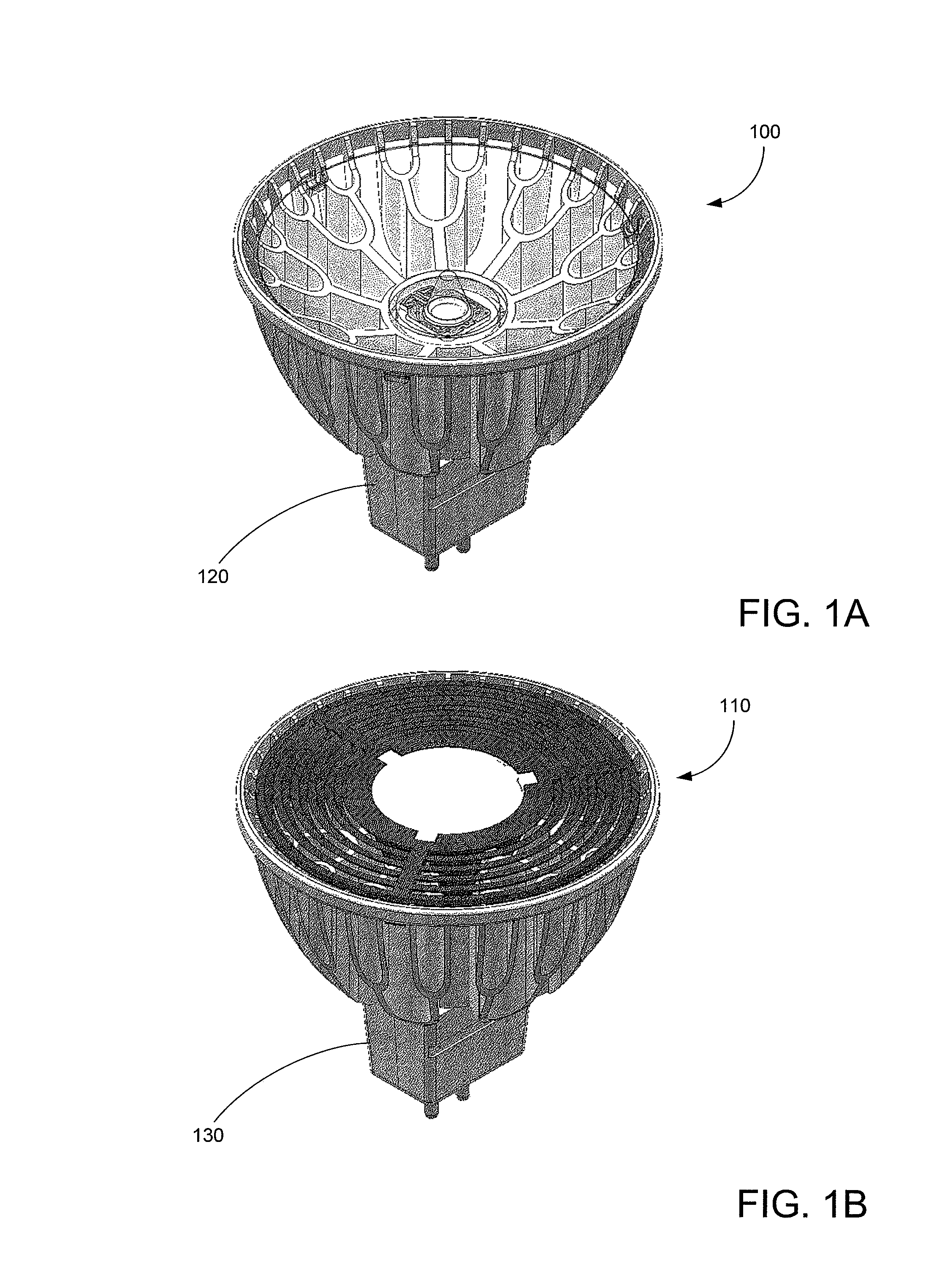
[0025]FIGS. 1A-B illustrate two embodiments of the present invention. More specifically, FIGS. 1A-B illustrate embodiments of MR-16 form factor compatible LED lighting sources 100 and 110 having GU 5.3 form factor compatible bases 120 and 130. MR-16 lighting sources typically operate with 12 volt alternating current (VAC). In the figures LED lighting source 100 is provides a spot light having a 10 degree beam, while LED lighting source 110 provides a flood light having a 25 to 40 degree beam.

[0026]An LED assembly such as described in the pending patent application described above may be used within LED lighting sources 100 and 110. LED lighting source 100 provides a peak output brightness from approximately 7600 to 8600 candelas (with approximately 360 to 400 lumens), with peak output brightness of approximately 1050 to 1400 candelas for a 40 degree flood light (approximately 510 to 650 lumens), and approximately 2300 to 2500 candelas for a 25 degree flood light (approximately 620 t...


PUM

PropertyMeasurementUnit
diameteraaaaaaaaaa
outer diameteraaaaaaaaaa
poweraaaaaaaaaa

Abstract

A method for forming a light source includes receiving an LED light module having a plurality of LEDs on a silicon substrate coupled to a flexible printed circuit and bonding the LED light module directly to a heat-sink with a thermal adhesive A base module with LED driver circuits is inserted into an interior channel of the heat sink and contacts of the LED driver circuits are connected to the LED light module.

Description

CROSS-REFERENCE TO RELATED APPLICATION[0001]The present application relates to pending patent application no. 61 / 301,193, filed Feb. 3, 2010, entitled “White Light Apparatus and Method,” incorporated herein by reference for all purposes.BACKGROUND OF THE INVENTION[0002]This invention relates to high efficiency lighting sources.[0003]The era of the Edison vacuum light bulb may soon end. In many countries, and in many states, incandescent bulbs are being replaced, and more efficient lighting sources mandated. Alternative light sources include fluorescent tubes, halogen, and light emitting diodes (LEDs). Despite the availability and improved efficiencies of these options, many people are reluctant to switch to these alternative light sources.[0004]The newer technologies have not been widely embraced for various reasons. One such reason is the use of toxic substances in the lighting source. As an example, fluorescent lighting sources typically rely upon mercury in a vapor form to produc...

Claims


Application Information

Patent Timeline
Patent Type & Authority Patents(United States)
IPC IPC(8): G05F1/00F21S4/00
CPCH05K1/189F21K9/1375F21V23/006F21V29/74F21V29/75F21V29/773F21V29/87F21V29/89F21Y2101/02Y10T29/49004H05K1/147H05K2201/10106F21V23/007F21V29/70Y10T29/4913Y10T29/49117H05K1/0203F21K9/23F21K9/238F21Y2115/10
Inventor SHUM, FRANK TIN CHUNGJUE, CLIFFORD
Owner KORRUS INC
Why Eureka
Try Eureka