Supercharge Your Innovation With Domain-Expert AI Agents!

User equipment terminal, base station, and uplink control channel configuration method

a user equipment and configuration method technology, applied in multiplex communication, signalling characterisation, wireless commuication services, etc., can solve the problems of radio resources being wasted, control information may not be transmitted in a single frequency block, radio resources reserved for the uplink shared channel may not be efficiently used, etc., to efficiently multiplex control information and efficiently use radio resources

Active Publication Date: 2012-12-04
NTT DOCOMO INC
View PDF5 Cites 2 Cited by
  • Summary
  • Abstract
  • Description
  • Claims
  • Application Information

AI Technical Summary

Benefits of technology

This approach enables efficient multiplexing of control information and effective use of radio resources, reducing waste and simplifying processing of the uplink shared channel.

Problems solved by technology

As a result, control information may not be transmitted in a single frequency block.
In this case, radio resources may be wasted, unless the uplink control channel and the uplink shared channel are efficiently assigned in the system band.
Furthermore, radio resources reserved for the uplink shared channel may not be efficiently used, unless channel quality information (CQI), acknowledge information (ACK / NACK), and scheduling request information are efficiently multiplexed into the uplink control channel.
As a result, processing of the uplink shared channel may be complicated.

Method used


Image

  • User equipment terminal, base station, and uplink control channel configuration method
  • User equipment terminal, base station, and uplink control channel configuration method
  • User equipment terminal, base station, and uplink control channel configuration method

Examples


Embodiment Construction

[0028][Description of Notations]

[0029]10 user equipment terminal

[0030]101 control information generating unit

[0031]103 control information multiplexing unit

[0032]105 downlink data receiving unit

[0033]20 base station

[0034]201 control channel assigning unit

[0035]203 control information separating unit

[0036]205 control information receiving unit

[0037]207 user-dedicated control channel information generating unit

[0038]209 user-common control channel information generating unit

[0039]211 control channel information multiplexing unit

BEST MODE OF CARRYING OUT THE INVENTION

[0040]With reference to the accompanying drawings, a description is given below with regard to embodiments of the present invention.

[0041]

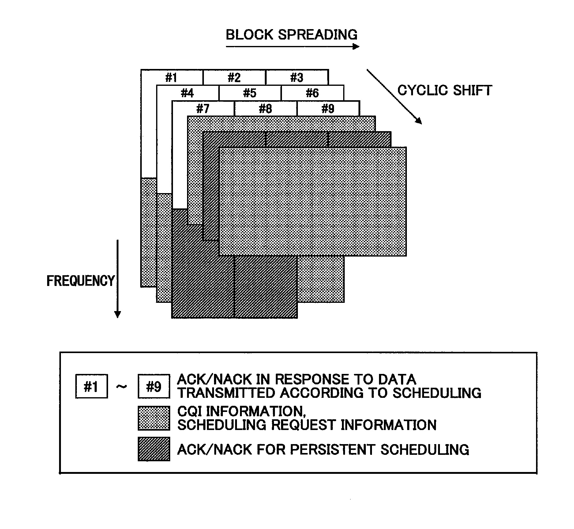
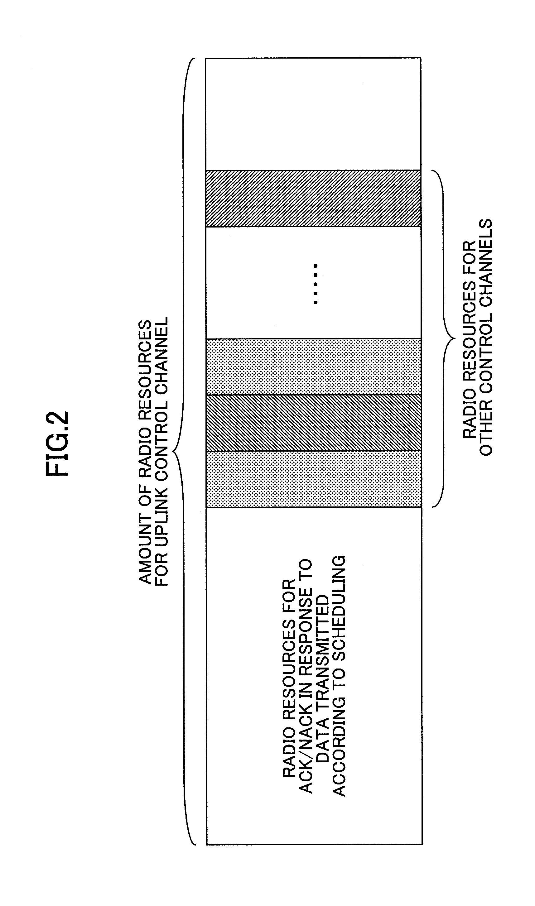
[0042]With reference to FIGS. 2 and 3, a configuration of uplink communication channels is described below. FIG. 2 shows a conceptual diagram illustrating a multiplexing scheme of control information into an uplink control channel in accordance with an embodiment of the present invention...


PUM


Abstract

A user equipment terminal for transmitting an uplink control channel to a base station according to a single carrier scheme includes a reception determining unit configured to determine reception of data, which are transmitted from the base station according to scheduling, and generate a reception determination result as first control information; and a control information multiplexing unit configured to assign the first control information to a first radio resource positioned at an end of a system band and assign second control information, which is transmitted with a radio resource dedicated to the user equipment terminal, to a predetermined position in a second radio resource adjacent to the first radio resource, to multiplex the first control information and the second control information into the uplink control channel. The present invention also relates to a base station and an uplink control channel configuration method.

Description

TECHNICAL FIELD[0001]The present invention relates to a user equipment terminal, a base station, and an uplink control channel configuration method.BACKGROUND ART[0002]As a next-generation communication system of the W-CDMA (Wideband Code Division Multiple Access) system and the HSDPA (High Speed Downlink Packet Access) system, an LTE (Long Term Evolution) system has been studied by 3GPP (3rd Generation Partnership Project). In the LTE system, a single carrier scheme (SC-FDMA: Single-Carrier Frequency Division Multiple Access) has been studied to be applied to uplink communications (see 3GPP TR 25.814 (V7.0.0), “Physical Layer Aspects for Evolved UTRA”, June 2006, for example).[0003]FIG. 1 shows an example configuration of uplink communication channels in LTE. As shown in FIG. 1, the system band is divided into plural frequency blocks. The frequency block is also referred to as a resource block, which is a minimum unit used in assigning a band. The time domain is divided into transm...

Claims


Application Information

Patent Timeline
Patent Type & Authority Patents(United States)
IPC IPC(8): H04W4/00
CPCH04J13/0059H04L1/0026H04L1/0027H04L1/16H04L1/1854H04L1/1861H04L5/0053H04L1/1607H04L5/0092H04W72/0453H04W72/12H04W72/21
Inventor KISHIYAMA, YOSHIHISAHIGUCHI, KENICHISAWAHASHI, MAMORU
Owner NTT DOCOMO INC
Features
  • R&D
  • Intellectual Property
  • Life Sciences
  • Materials
  • Tech Scout
  • Unparalleled Data Quality
  • Higher Quality Content
  • 60% Fewer Hallucinations
Learn More