Image forming apparatus

a technology of image forming apparatus and forming apparatus, which is applied in the direction of electrographic process apparatus, instruments, corona discharge, etc., can solve the problems of image defect, impact-caused unevenness, and increase variation, so as to achieve stable remedying image defect, no disadvantage, and simple constitution

Active Publication Date: 2012-12-04
CANON KK
View PDF4 Cites 1 Cited by
  • Summary
  • Abstract
  • Description
  • Claims
  • Application Information

AI Technical Summary

Benefits of technology

[0005]A principal object of the present invention is to provide a high-quality image forming apparatus capable of stably remedying image defect, by a simple constitution with no disadvantage, caused due to image defect generated by temporary speed variation of an intermediary transfer member resulting from load variation of the intermediary transfer member. Specifically, the present invention is different from the above-described conventional constitutions in which the speed variation itself of the intermediary transfer member is suppressed, and suppresses density variation generated by the speed variation.
[0006]Therefore, a specific object of the present invention is to provide an image forming apparatus capable of stably achieving, compared with the above-described conventional constitutions, an effect irrespective of a generating mechanism and a condition such as the type of paper or a print mode and capable of improving an image quality with less disadvantage and less increase in cost.
[0007]Another specific object of the present invention is to provide an image forming apparatus capable of improving the image quality with no disadvantage even in the case where speed variation of the intermediary transfer member is particularly large.
[0008]A further specific object of the present invention is to provide an image forming apparatus having an advantage such that there is no need to consider a disadvantage of an occurrence of moire due to interference between dithering and writing correction by light exposure.

Problems solved by technology

When the large speed variation occurs with respect to the intermediary transfer belt, density variation of the developer image occurs at the time when the developer image is transferred from the photosensitive drum onto the intermediary transfer belt (primary transfer) to result in image defect.
As a result, the load variation is increased, so that the impact-caused unevenness is liable to occur.
Particularly, with respect to a sheet having an uneven surface configuration, there is a tendency that a transfer efficiency is liable to be lowered at a recessed portion.
Also in this case, the tangential force applied from the sheet onto the intermediary transfer belt is increased to result in the large load variation, so that the impact-caused unevenness is liable to occur.
However, the constitution proposed in JP-A 2007-147758 is not applicable to the impact-caused unevenness occurring due to the load variation when the trailing end of paper comes out of the secondary transfer nip and is not applicable to the impact-caused unevenness occurring due to a factor other than conveyance of paper, so that an applicable condition is limited.
The constitution proposed in JP-A 2007-328094 is complicated and newly requires a plurality of additional parts, thus leading to an increase in cost.
As described above, when the speed variation of the intermediary transfer member is intended to be suppressed, the above-described conventional constitutions are accompanied with problems such that the constitutions are not applicable to some impact-caused unevenness depending on a generating mechanism, that an effect of the constitution is limited depending on the type of paper (sheet) or a print mode, and that the constitutions lead to the increase in cost.
For that reason, there is a possibility that the correction control interferes with dithering to generate moire (interference fringe).

Method used


Image

  • Image forming apparatus
  • Image forming apparatus
  • Image forming apparatus

Examples


embodiment 1

(Embodiment 1)

(1) Image Forming Apparatus

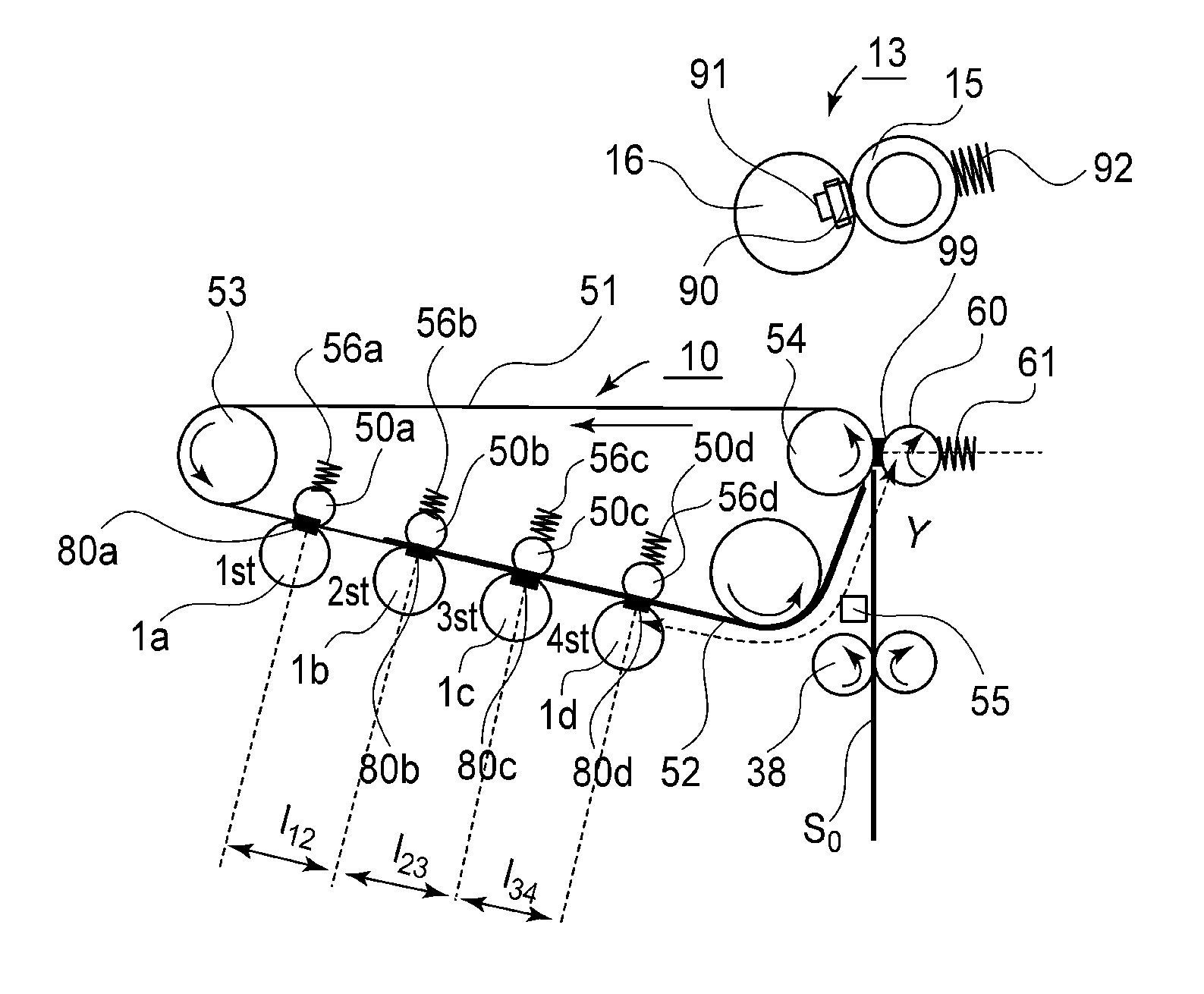
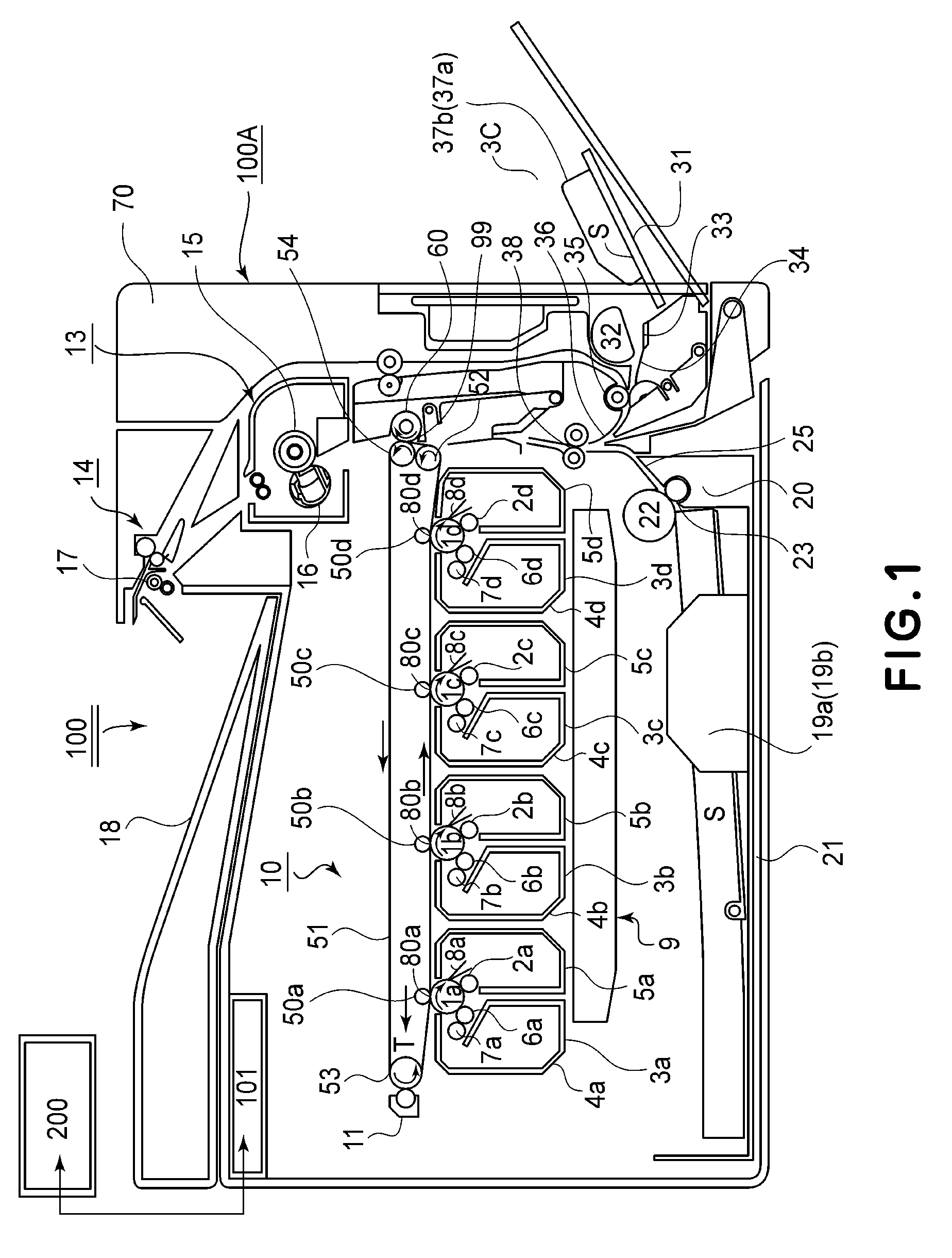
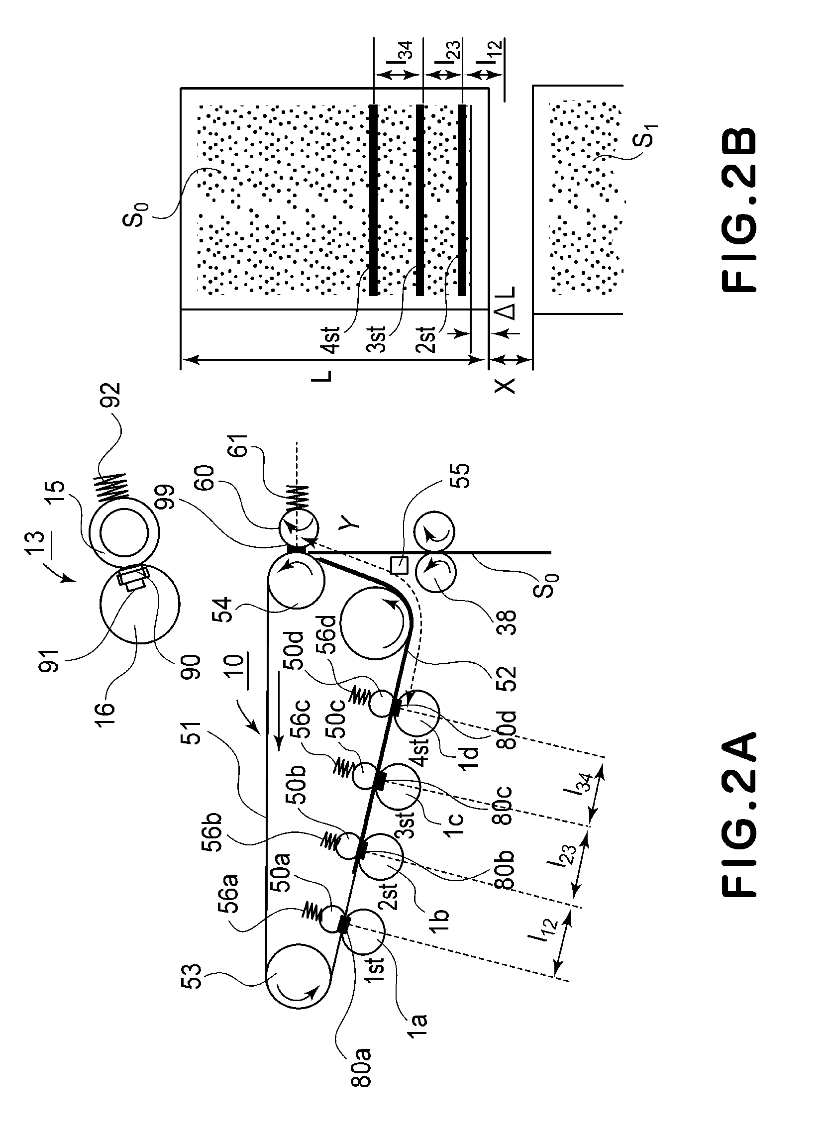
[0027]FIG. 1 is a schematic illustration of an embodiment of the image forming apparatus according to the present invention. An image forming apparatus 100 is a color printer of an electrophotographic type. The image forming apparatus 100 effect color image formation or monochromatic image formation on a sheet-like recording material as a recording medium (hereinafter referred to as a “sheet”) on the basis of an electrical image signal input from a host device 200 into a control portion (a control means or a control circuit control portion) 101. The host device 200 is, e.g., a personal computer, an image reader, or the like. The control portion 101 includes a CPU (computing portion), an ROM (storing means), and the like and performs various electrical information transfer between itself and the host device 200 or an operating portion (not shown) of the image forming apparatus 100. Further, control portion 101 effects centralized control of an...

embodiment 2

(Embodiment 2)

[0064]In Embodiment 1, the method of decreasing the absolute value of the developing bias by the predetermined amount (ΔV) for the predetermined time (Δt) with timing when the leading end of the sheet enters the T2 nip 99 is described. However, there is the need to increase the developing bias change amount ΔV when the speed variation of the belt 51 is large, such as when the constitution in which the nip pressure in the T2 nip 99 is particularly large is employed or when the thick paper is passed through the T2 nip 99 in the monochromatic mode. In that case, when only the absolute value of the developing bias is changed, there is a possibility of an occurrence of a problem such that a difference of the developing bias absolute value from other bias set values (those of the developing bias, the RS bias and the blade bias) is largely changed. For example, when the difference between the developing blade bias and the developing bias is excessively small, the toner is dep...

embodiment 3

(Embodiment 3)

[0066]The impact-caused unevenness due to the speed variation of the intermediary transfer belt is also generated in cases other than the case where the sheet enters the transfer portion or comes out of the transfer portion in the in-line type full-color laser beam printer described in Embodiment 1.

[0067]In this embodiment, the case where the present invention is applied to the impact-caused unevenness generated due to the speed variation by the contact and separation of the secondary transfer roller or the cleaning roller when a four color-based (four-pass) full-color laser beam printer of the electrophotographic type is used will be described.

[0068]FIG. 9 is a schematic sectional view showing a structure of an image forming apparatus 200 according to the present invention.

[0069]The image forming apparatus 200 shown in FIG. 9 includes a drum-type electrophotographic photosensitive member 201 as a first image bearing member (hereinafter referred to as a photosensitive ...


PUM


Abstract

An image forming apparatus includes a rotatable image bearing member; a developing device, including a developer carrying member and developing bias application means for applying a developing bias for developing a developer image; a rotatable intermediary transfer member; a primary transfer member for forming a primary transfer nip and for transferring the developer image from the image bearing member onto the intermediary transfer member; a secondary transfer member for secondary-transferring the developer image from the intermediary transfer member onto a recording material; wherein an area of the image bearing member includes a first area at least containing an area located in primary transfer nip at a time when a speed of the intermediary transfer member is temporarily decreased and includes a second area located in the primary transfer nip when there is no temporary change in speed; and a control device for controlling a developing bias.

Description

FIELD OF THE INVENTION AND RELATED ART[0001]The present invention relates to an image forming apparatus for forming an image on a recording material or medium.[0002]In recent years, the image forming apparatus such as a laser printer or a copying machine is required that it has functions of increasing a speed for improving productivity and of improving image qualities and the like functions and that it can support the recording material (hereinafter referred to as a sheet) of various types. For example, in a color laser printer, a method in which an intermediary transfer belt (intermediary transfer member) capable of carrying a plurality of developer images has been employed. In this method, the number of sheets subjected to image formation per unit time can be increased and a constitution thereof is suitable for improvement in image quality when a color image is formed. In the constitution of the method, a developer image is formed on a photosensitive drum as an image bearing membe...

Claims


Application Information

Patent Timeline
Patent Type & Authority Patents(United States)
IPC IPC(8): G03G15/06
CPCG03G15/065G03G15/1605G03G2215/0132
Inventor YANAGI, YUYA
Owner CANON KK
Why Eureka
Try Eureka