Enhanced piccolo ducting with sidewall air outlets

Active Publication Date: 2012-12-11
AIRBUS OPERATIONS GMBH
View PDF9 Cites 10 Cited by
  • Summary
  • Abstract
  • Description
  • Claims
  • Application Information

AI Technical Summary

Benefits of technology

[0019]When the system according to the invention for ventilating an aircraft cabin is mounted in an aircraft, an air outlet is preferably provided at least in a partial region of the aircraft cabin in every second space between two ribs of the aircraft cabin, that is in every second region of the aircraft cabin bounded by two ribs adjacent to one another. Such a configuration of the ventilating system according to the invention ensures a sufficient air supply Into the aircraft cabin in the second operating state of the ventilating system. At the same time, a certain flexibility in the cabin design and in the construction of the ventilating system is retained, since it is possible to shift individual air outlets to a space between two ribs which was previously not provided with an air outlet. For example, fittings which are to be positioned only in certain regions of the aircraft cabin may make it necessary to shift the air outlets from one space between two ribs to an adjacent space between two ribs. Furthermore, spaces between two ribs of one aircraft sidewall which are not provided with an air outlet may be used to receive air outlets which are actually intended for arrangement in the region of the opposite aircraft sidewall, if they cannot be installed there, for example in the region of a door or the like. It can thus be ensured that the same quantity of air can always be introduced into the individual regions of the aircraft cabin without excessively increasing the blowing-out speed of the air from the air outlets.
[0020]The air supply pipe may be arranged substantially centrally or off-centre in the region of a ceiling of the aircraft cabin when the ventilating system according to the invention is mounted in an aircraft. An arrangement of the air supply pipe in the region of the aircraft cabin ceiling enables a particularly installation-space-saving installation of the air supply pipe and of the air distribution lines, and also of the connecting lines to be connected to the air distribution lines in the second operating state of the ventilating system.
[0021]An orifice may be arranged in at least some of the air distribution lines The orifice serves to control as desired the flow properties of the air flow exiting from the air distribution lines. Preferably, the orifice is adapted also to completely close the air distribution line, if required. It is thereby possib

Problems solved by technology

Owing to the blowing-out angle of the air from the piccolo pipe, intensive air mixing occurs in the aircraft cabin, making it virtually impossible to control different temperature zones.
Owing to their high air blowing-out speeds which are advantageously usable in a cargo aircraft, ventilating systems equipped with a piccolo pipe are, however, unsuitable for use in a passenger aircraft.
The disadvantages of known ventilating systems suita

Method used


Image

  • Enhanced piccolo ducting with sidewall air outlets
  • Enhanced piccolo ducting with sidewall air outlets
  • Enhanced piccolo ducting with sidewall air outlets

Examples


Example

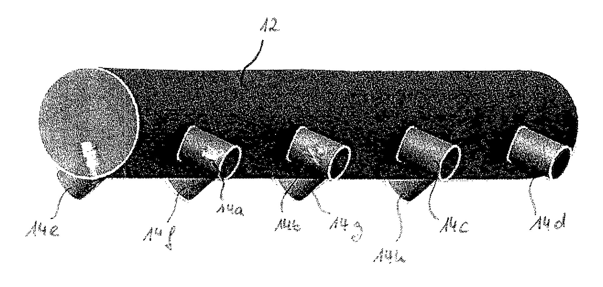
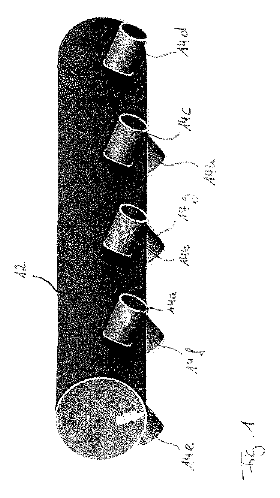
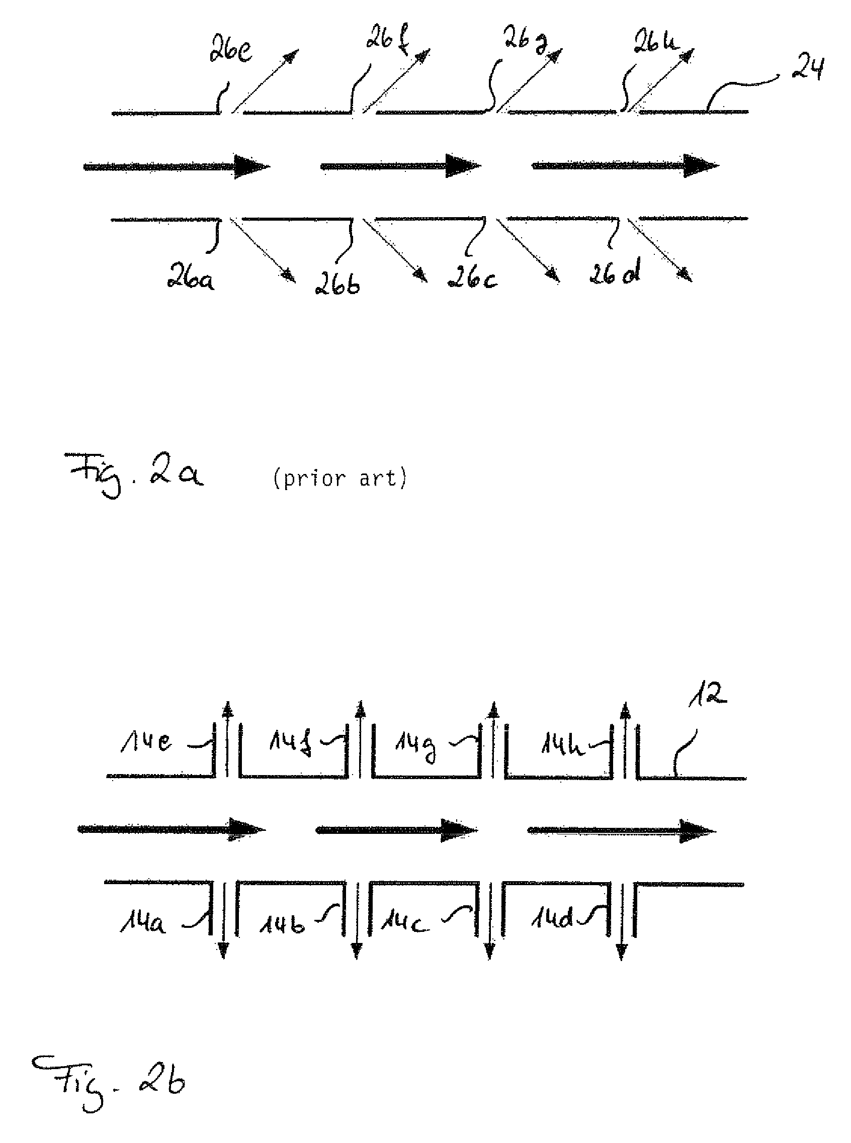
[0034]In the figures, a system for ventilating an aircraft cabin is denoted generally by 10. The ventilating system 10 comprises an air supply pipe 12 connected to an air source, not illustrated specifically. In the operation of the ventilating system 10, air flows through the air supply pipe 12. The air supply pipe 12 is shown with a round cross-section in FIGS. 1, 3, 4 and 5. The air supply pipe 12 may, however, also have an oval cross-section or any other cross-section.

[0035]A plurality of air distribution lines 14a-14h designed in the form of connecting stubs branch off from the air supply pipe 12. When the air supply pipe 12 and the air distribution lines 14a-14h are mounted in an aircraft in the region of a ceiling 15 of the aircraft cabin, a first group of air distribution lines 14a-14d extends substantially in the direction of a first aircraft cabin sidewall 16. In contrast, when the air supply pipe 12 and the air distribution lines 14a-14h are mounted in an aircraft, a seco...


PUM


Abstract

A system for ventilating an aircraft cabin includes an air supply pipe connected to an air source, and a plurality of air distribution lines branching off from the air supply pipe. In a first operating state, the ventilating system is adapted to blow out the air, flowing through the air supply pipe, directly from the air distribution lines into the aircraft cabin. In contrast, in a second operating state of the ventilating system, at least some of the air distribution lines are connected to connecting lines which supply the air, flowing through the air supply pipe, to air outlets arranged in a distributed manner in the aircraft cabin.

Description

[0001]This application claims priority to U.S. Provisional Patent Application No. 61 / 057,265, filed on May 30, 2008; and / or German Patent Application No. 102008026093.2, filed on May 30, 2008.TECHNICAL FIELD[0002]The present invention relates to a system and a method for ventilating an aircraft cabin.BACKGROUND[0003]Systems, employed in cargo aircraft, for ventilating an aircraft cabin used as a cargo compartment comprise at present usually a piccolo pipe installed directly beneath the cabin ceiling. The piccolo pipe is provided with a plurality of air outlet openings, through which air flowing through the piccolo pipe can be blown out of the piccolo to pipe into the aircraft cabin. A ventilating system having a piccolo pipe as the central element for supplying ventilating air into an aircraft cabin is distinguished by a low weight and a low installation space volume. Furthermore, air blowing-out speeds of up to 15 m / s are attained with a ventilating system of this type. Owing to th...

Claims


Application Information

Patent Timeline
IPC IPC(8): B64D13/00
CPCB64D13/00B64D2013/0625B64D2013/0655Y02T50/44Y02T50/40
Inventor REISBACH, SVEN
Owner AIRBUS OPERATIONS GMBH
Why Eureka
Try Eureka