
Turbo-type vertical shaft wind mill

A turbine type and wind turbine technology, applied in the field of wind energy utilization, can solve the problems of easily damaged blades, and achieve the effects of improving wind energy utilization efficiency, improving wind gathering performance, and increasing contact area

Inactive Publication Date: 2011-06-22
DALIAN UNIV OF TECH
View PDF0 Cites 2 Cited by
  • Summary
  • Abstract
  • Description
  • Claims
  • Application Information

AI Technical Summary

Problems solved by technology

Therefore, in order to improve the wind energy utilization efficiency of vertical axis wind turbines, shielded flat-blade wind turbines, flat-blade swing wind turbines and S-shaped impeller wind turbines have been proposed, but the above-mentioned wind turbines may only use half of the impeller of the wind turbine. drive, or the blades are easily damaged due to frequent swings, therefore, it is necessary to develop a new type of vertical axis wind turbine

Method used


Image

  • Turbo-type vertical shaft wind mill
  • Turbo-type vertical shaft wind mill
  • Turbo-type vertical shaft wind mill

Examples


Embodiment Construction

[0017] Specific embodiments of the present invention will be described in detail below in conjunction with technical solutions and accompanying drawings.

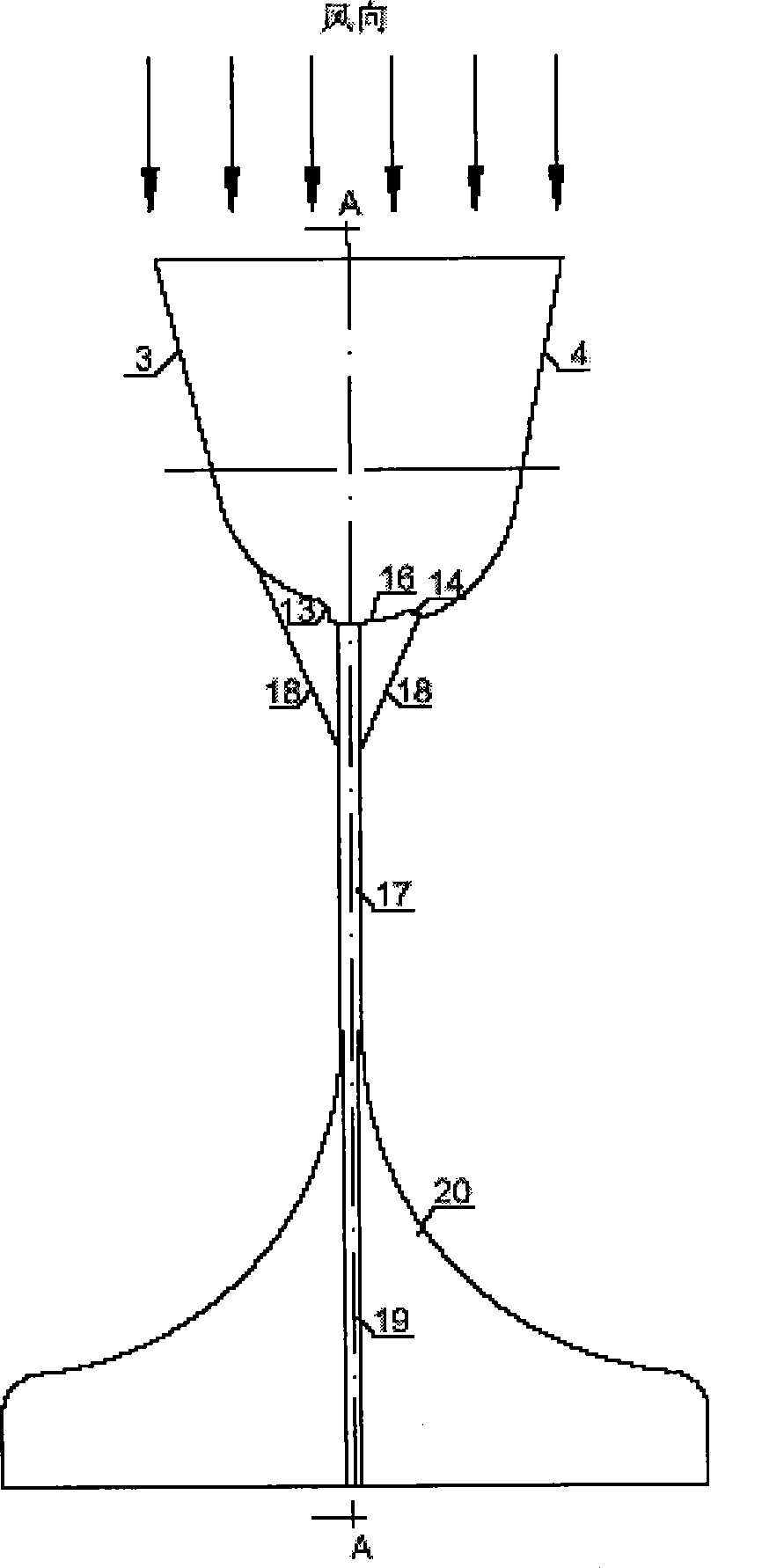
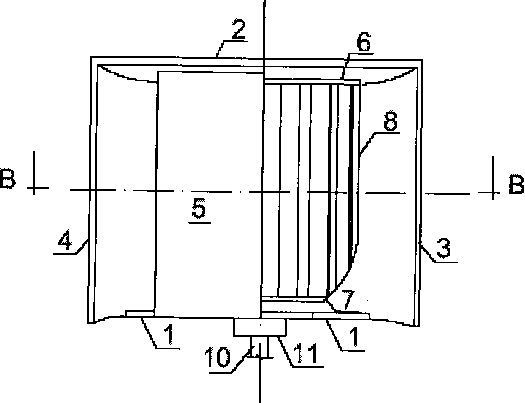
[0018] The turbine-type vertical axis wind power machine of the present invention is mainly composed of the wind collector bottom plate 1, the wind collector top plate 2, the left wind collector plate 3, the right wind collector plate 4, the volute 5, the blade upper hoop 6, the blade lower hoop 7, Blade 8, blade inner cylinder 9, shaft 10, wind collector bearing 11, impeller bearing 12, left wind collector tail fin 13, right wind collector deflector 14, right air inlet 15, wind collector outlet 16, Guide rod 17, guide rod support 18, vertical guide tail 19 and lateral guide tail 20 form. The upper blade hoop 6, the lower blade hoop 7 and the blade 8 are welded to form the impeller; the shaft 10 of the impeller is installed vertically, connected with the air collector bottom plate 1 through the wind collector bearing 11, an...


PUM


Abstract

The invention discloses a turbo type vertical shaft windmill, belonging to the field of wind energy utilization. The invention is characterized in that the windmill comprises a wind collector soleplate, a wind collector top slab, a left wind collecting plate, a right wind collecting plate, a volute case, an upper blade hoop, a lower blade hoop, a blade, a blade inner barrel, a shaft, a wind collector bearing, a tail fin of the left wind collecting plate, a guide plate of the right wind collecting plate, a right ventilation inlet, an air outlet of the wind collector, a guide lever, a guide lever bracket, a vertical guiding tail fin and a transverse tail fin. The shaft of the blade is arranged vertically; the wind collector soleplate, the wind collector top slab, the left wind collecting plate, the right wind collecting plate and the volute case form a wind collector; the volute case, the tail fin of the left wind collecting plate and the guide plate of the right wind collecting plate form a wind guiding device; the guide lever, the vertical guiding tail fin and the transverse tail fin form a wind mechanism. The invention has the advantages that the air current flows into the blade along the left wind collecting plate and the right wind collecting plate, and has the characteristics of good wind collecting performance, high utilization coefficient of the wind energy, and low starting wind speed.

Description

technical field [0001] The invention belongs to the field of wind energy utilization, and relates to components such as a wind turbine, a wind collector, an impeller and the like in a vertical shaft wind power generator. Background technique [0002] Wind turbines are key equipment for wind power generation. At present, wind turbines include horizontal-axis wind turbines and vertical-axis wind turbines. Horizontal-axis wind turbines are used in both large-scale wind turbines and small-scale wind turbines. In the application process of horizontal-axis wind turbines, there are tower loads and balance. Poor performance, need for wind mechanism and other deficiencies. The vertical axis wind turbine generally does not need a wind-facing mechanism, and the generator can be installed on the ground to reduce the load on the tower. The cost is low and it is easy to maintain and maintain. Therefore, the vertical axis wind turbine has attracted widespread attention in recent years. V...

Claims


Application Information

Patent Timeline
Patent Type & Authority Patents(China)
IPC IPC(8): F03D3/00F03D3/06F03D3/04F03D11/00F03D80/00
CPCY02E10/74
Inventor 张吉礼马良栋牟宪民
Owner DALIAN UNIV OF TECH
Learn More