Ship with a contaminant separation device

a separation device and contaminant technology, applied in the field of ships, can solve the problems of increased danger of asphyxiation, constant fire hazards, and carcinogenic vapours

Inactive Publication Date: 2012-12-11
P F FAROE MARITIME TECHNIC
View PDF17 Cites 1 Cited by
  • Summary
  • Abstract
  • Description
  • Claims
  • Application Information

AI Technical Summary

Benefits of technology

[0007]The object of the present invention is to provide a reliable system for cleaning contaminated bilge water accumulating inside the hull of a ship in the engine room by separating the fluid contaminants from the bilge water, and to overcome the above mentioned shortcomings.

Problems solved by technology

The above-mentioned fluid organic contaminants are hazardous to the health of staff working in a machinery space, since at least some of the contaminants may evaporate, creating carcinogenic vapours in the air of the machinery space.
Furthermore, the contaminants are inflammable and have a tendency to concentrate at the surface of the bilge water, thereby causing a constant fire hazard.
In case of fire, the contaminants develop hazardous gases and heavy smoke preventing any effective fire fighting with the additional danger of asphyxiation for those caught in the smoke.
Such an accident is particularly serious when happening on a ship at sea, far from any harbour and easy rescue.
In addition, the contaminants are potentially dangerous for the environment, as they pollute the sea, coasts, and harbours, when discharged directly into the sea.
However, the proposed systems are often very expensive, suffer from complexity, limited capacity at peak load, and / or lack of reliability, and have to be put out of operation frequently either for maintenance or due to system failure.
As a consequence, the chosen solution is often still to simply discharge the contaminated bilge water directly into the sea disregarding all environmental regulations and the risk of serious punishment imposed on such illegal discharge by many countries.

Method used


Image

  • Ship with a contaminant separation device
  • Ship with a contaminant separation device
  • Ship with a contaminant separation device

Examples


Embodiment Construction

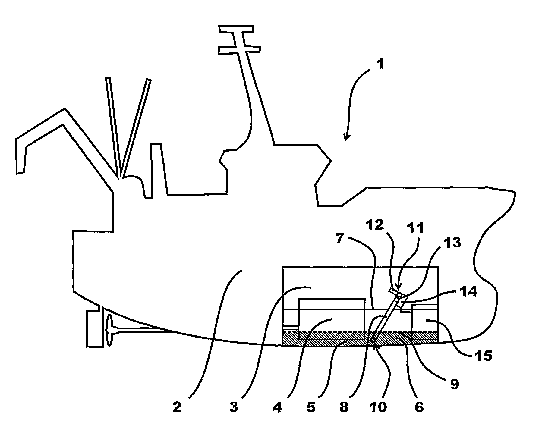
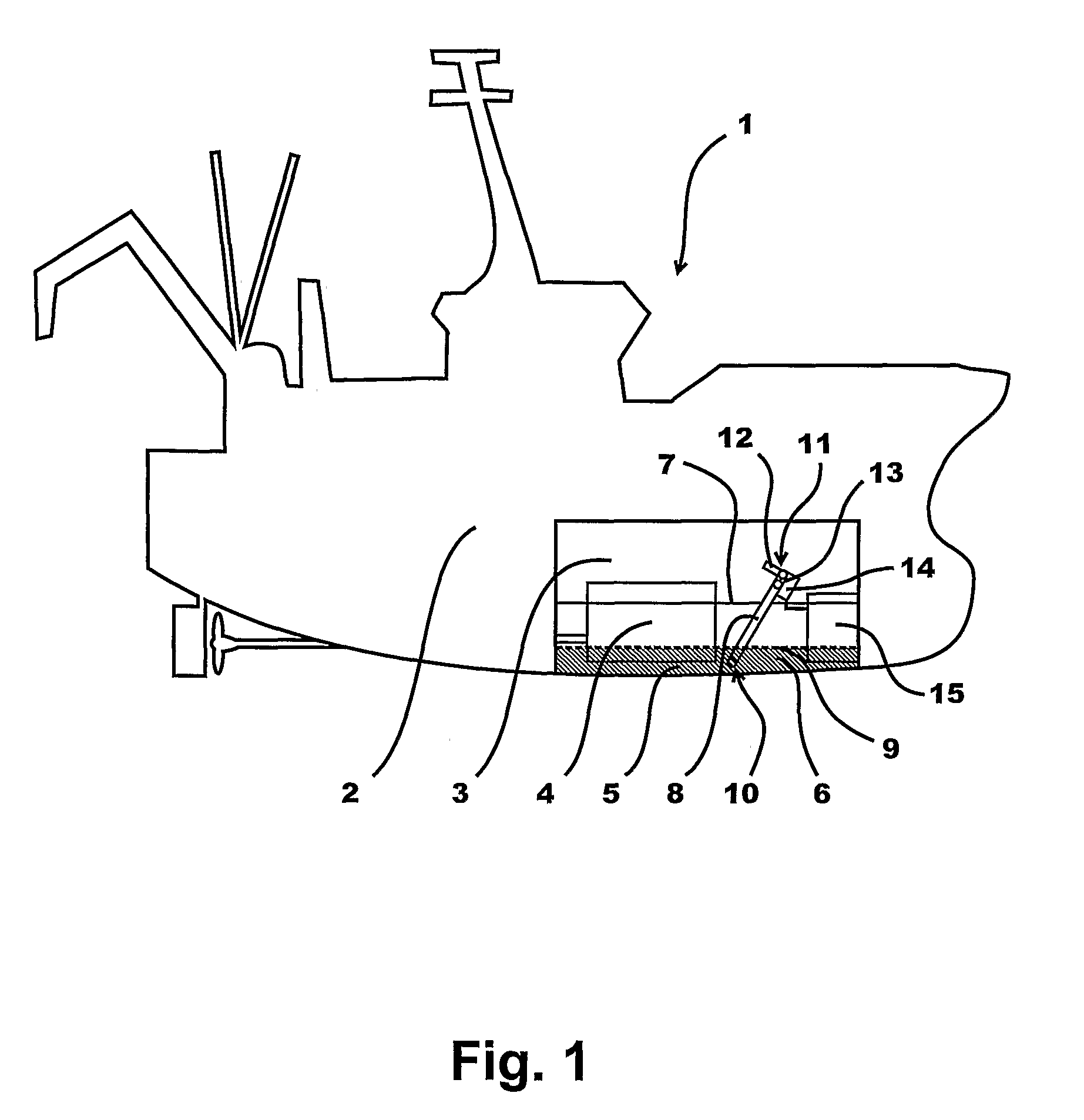
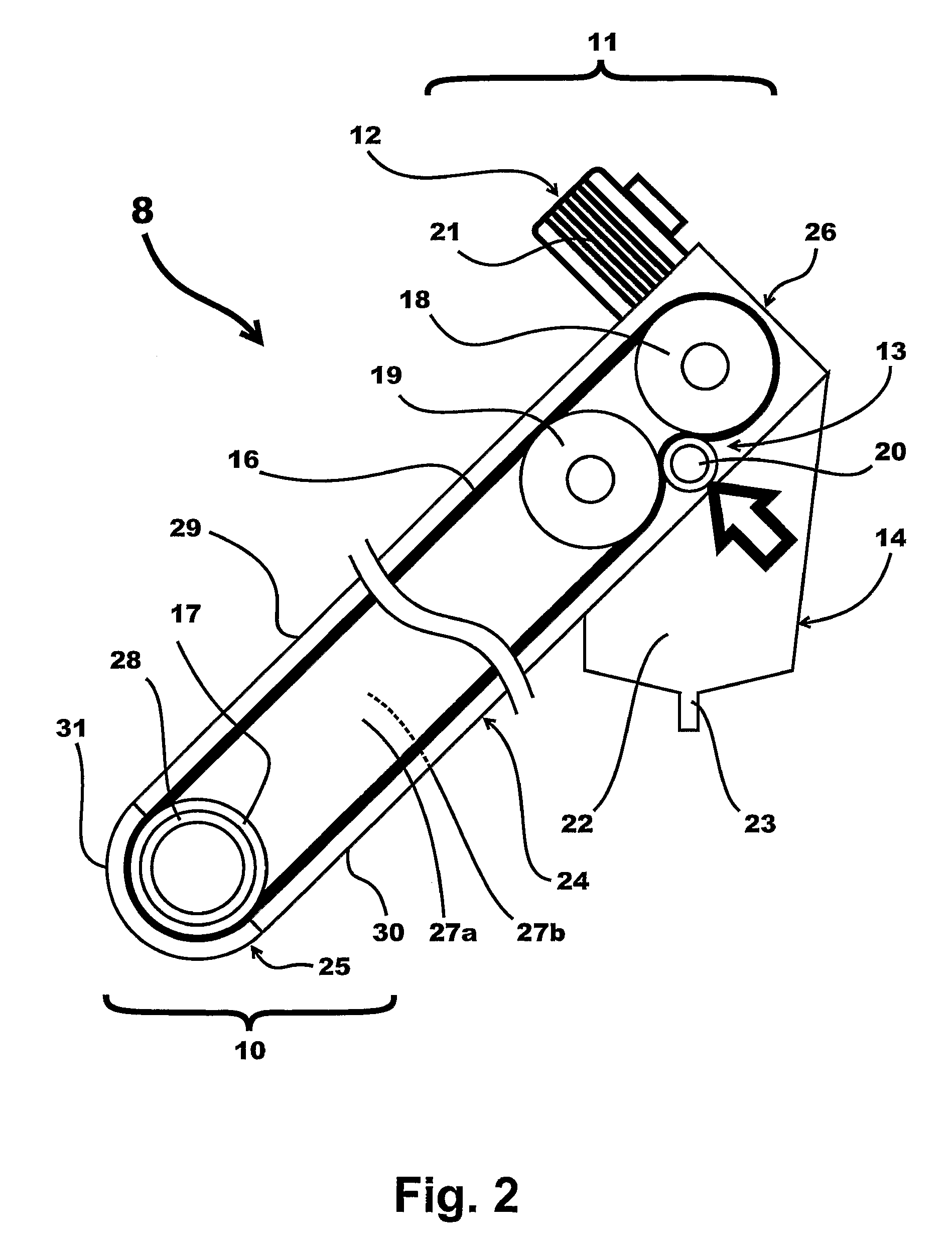
[0090]FIG. 1 schematically shows a ship 1 with a hull 2 comprising a engine room 3 accommodating machinery, such as the engine 4. The engine room 3 is provided with a bilge water sump 5 collecting bilge water 6 and contaminants. The bilge water sump 5 may be covered by an arrangement of floor panels 7. A first contaminant separation device with a conveyor arrangement 8 comprising an endless belt 16 extends through an opening in the floor panels 7 into the bilge water sump 5 and below the surface 9 of the bilge water 6. A first portion 10 of the conveyor arrangement 8 is thereby at least partially submerged in the bilge water 6. A second portion 11 of the conveyor arrangement 8 comprising driving means 12, releasing means 13, and collecting means 14 is arranged above the floor panels 7. The collecting means 14 may be connected to a waste reservoir 15 for receiving the collected contaminants.

[0091]The conveyor arrangement 8 may be mounted in a frame fixed to the floor panel arrangemen...


PUM

PropertyMeasurementUnit
volumeaaaaaaaaaa
open timeaaaaaaaaaa
close timeaaaaaaaaaa

Abstract

A ship comprises a bilge water sump collecting bilge water and contaminants. A first contaminant separation device is provided comprising a conveyor arrangement with an endless belt comprising adsorbing / absorbing material. The conveyor arrangement has a first portion submergible into the bilge water and contaminants in the bilge water sump, and a second portion being spaced from the first portion and provided with means for releasing adsorbed / absorbed contaminants from the conveyor belt and means for collecting the contaminants released. The conveyor arrangement is further provided with means for driving the endless belt along a moving path defined by guiding means.

Description

[0001]This is a National Phase Application filed under 35 USC 371 of International Application No. PCT / DK2008 / 000307, filed on Aug. 28, 2008, an application claiming foreign priority benefits under 35 USC 119 of Danish Application No. PA 2007 01226, filed on Aug. 29, 2007, and claiming foreign priority benefits under 35 USC 119 of Danish Application No. PA 2008 00486, filed on Apr. 3, 2008, the content of each of which is hereby incorporated herein by reference in its entirety.TECHNICAL FIELD[0002]The invention relates to a ship comprising a bilge water sump for collecting bilge water and contaminants, said bilge water sump optionally being covered by one or more floor panels.BACKGROUND[0003]Inside a ship, waste water from cleaning and / or from small leakages in the hull of the ship accumulates—typically at the bottom of the hull or in a sump provided for that purpose. Particularly in the engine room of the ship, waste water accumulates together with all kinds of contaminants in the ...

Claims


Application Information

Patent Timeline
Patent Type & Authority Patents(United States)
IPC IPC(8): C02F1/00
CPCB63J4/004B63B17/0018B63B17/06
Inventor JOENSEN, KAJ
Owner P F FAROE MARITIME TECHNIC
Why Eureka
Try Eureka