Power transmission system with continuously variable speed control

a technology of power transmission system and output member, which is applied in the direction of fluid gearing, gearing, gearing equipment, etc., can solve the problems of low power transmission system, system is not without its own drawbacks, and is typically limited to small applications with relatively low horsepower, so as to achieve maximum fuel economy, reduce the speed of the output member, and increase the transmission torque

Inactive Publication Date: 2008-04-17
EPI ENERGY LTD A TEXAS
View PDF27 Cites 2 Cited by
  • Summary
  • Abstract
  • Description
  • Claims
  • Application Information

AI Technical Summary

Benefits of technology

[0025]The result is a continuously variable transmission system with capabilities unmatched by the prior art. First, through a novel configuration of components, the present invention allows the prime mover to continuously operate at the user's desired speed and torque, whether the application requires a particularly high transmission of torque throughout its specified operating speeds or whether the application calls for the prime mover to operate at its peak efficiency for maximum fuel economy. That is, in operation, the present system allows for the prime mover to be set and held at the optimum speed for which the application calls. When the secondary input member is fixed to prevent rotation of the secondary input shaft, the speed is reduced through the two (or more) stage reduction system of low friction rollers to the maximum output speed and corresponding desired torque increase of the output shaft. While holding the prime mover constant, the secondary input member, which may be driven by either an electric or hydraulic motor, is ramped up, resulting in a further reduction in speed of the output member, while keeping the output member at a constant torque. Therefore, the system allows for an infinitely variable, step-less, variation in output speed, while maintaining the prime mover at a constant speed and while maintaining the available torque to the output member at a constant level as well. Furthermore, the system can be used to retard speed or provide breaking to a device connected to the output member by continuing to ramp up the speed of the secondary input until the rotation of the output member is reversed.
[0026]Secondly, because of its compact design, and the robustness of its component parts, the present invention is able to transmit much higher torque and horsepower than current continuously variable transmission systems, while maintaining a much smaller envelope and lighter operating weight. Current continuously variable operating systems depend on sets of conical discs and either belts or rollers to transmit the torque loads. These types of systems, as previously mentioned, result in large, heavy systems compared to the torque loads they are capable of transmitting. By contrast, the present invention has an extremely high torque to size / weight ratio because the present invention is merely dependent upon the size of the driver and driven discs and the eccentricity of each. Further, because torque is transmitted by a series of low-friction rolling members, large torque transmitting members are not necessary.
[0027]Additionally, the mechanical efficiency of the present invention is extremely high because of the near elimination of friction within the system as compared to current continuously variable power transmission systems. Whereas, most continuously variable transmission systems depend on friction for the transmission of the torque, most of the newer, electromechanical systems use planetary gear systems, as previously mentioned. In the former, a reduction in friction results in slippage and a corresponding reduction in efficiency, while in the latter, a significant amount of efficiency is lost due to the “sliding” friction generated between the mating teeth. By contrast, all torque transfer in the present system is accomplished through low-friction, rolling engagement; therefore, because the present invention completely eliminates the “sliding” or slipping friction effects of the prior art, the present invention is able to operate at a significantly higher efficiency.
[0028]The present invention is also able to withstand much higher loading (including impact loading) than prior art continuously variable transmission systems. In belt systems, all loading is transferred via belts; thus, the system is limited by the tensile strength of belt materials. In toroidal systems, all loading is transferred via friction rollers; thus, the system is limited by the frictional loading between the rollers and the discs. Finally, in electromechanical gearing systems, all loading is transferred via a single gear tooth; thus, these systems are limited by the strength of materials and the loading that a single gear tooth can withstand. In the present invention, loading is evenly distributed among multiple, rolling members, which, in turn, allows the system to withstand much higher loading than its traditional counterparts. Not only does this result in a more robust system (compared to the size of the system), but it also results in a more reliable system because damage to one rolling member does not result in total system failure whereas a broken gear tooth, belt, or roller does lead to total system failure in the known prior art systems. Therefore, the present design is much more durable and reliable than currently available continuously variable transmission systems.
[0029]Finally, the present invention, in its preferred embodiment, is extremely cost effective in view of the prior art of continuously variable transmission systems. The novel design of the present invention provides for a simple and cost-effective manufacturing process as opposed to more traditional manufacturing techniques applied to current power transmission systems. Whereas the traditional manufacturing methods of casting and extensive machining of a number of different sized components is laborious, time-consuming, and expensive, the present invention requires relatively very little in the way of lead or production costs. In the present invention, both the housing and the internal components of the device are laminated. That is, each component is comprised of a plurality of relatively thin pieces of source material, generally consisting of a metal alloy or some other suitably rigid material, which are individually cut and sandwiched together using an affixing means, such as pins, screws, or other bonding techniques, to form the final primary components. Production by way of lamination greatly reduces both start up time and cost as well as production time and cost without sacrificing strength or quality. Start up time and cost are reduced by eliminating the need for long-lead casting and machining equipment. Correspondingly, production time and cost are reduced by eliminating the need for stocking and using materials of multiple thicknesses and by eliminating the need for extensive machining and highly skilled machinists to produce final primary components. Thus, when compared to the prior art continuously variable power transmission systems, the present invention provides a substantially more cost-effective device than is presently available.
[0030]In summary, the present invention provides a highly cost-effective, compact, and reliable continuously variable power transmission system capable of withstanding significantly higher torque loads than that of the prior art.

Problems solved by technology

First, conventional power transmission systems employ the use of multiple gear sets and clutching devices.
Consequently, the prime mover cannot always operate at its most efficient speed, resulting in a less than ideal power transmission system.
These present continuously variable transmission systems provide a significant advantage over conventional systems; however, these systems are not without their own drawbacks.
This type of system works well for its intended purpose and provides many advantages including its efficiency and simplicity; however, several drawbacks of the belt driven continuously variable transmission exists as well.
First, this type of system is typically limited to small, relatively low horsepower applications because of its reliance on the belt for full power transmission.
In such a system, the belt can stretch (resulting in slippage and efficiency loss) or break resulting in complete power failure.
Additionally, the system is limited by its size.
The typical belt system is large in size and weight, limiting its useful applications to light stationary or light mobile equipment.
When the rollers are in contact with the input disc near the center, they must contact the output disc near the rim, resulting in a reduction in speed and an increase in torque.
When the rollers contact the input disc near the rim, they must contact the output disc near the center, resulting in an increase in speed and a decrease in torque.
This type of system, similarly to the belt system, suffers from drawbacks associated with its limited size and scope.
Toroidal continuously variable power transmissions are unable to handle large torque loads, and are quite heavy, limiting it to light stationary and mobile equipment as well.
However, hydrostatic drives also have several drawbacks.
The hydrostatic power transmission systems are noisy and operate at very low efficiency.
Additionally, hydrostatic power transmission systems are prone to contamination, which can result in efficiency loss or catastrophic system failure.
However, a number of inherent deficiencies exist in this type of mechanical gear train that are well known in the art.
For instance, the efficiency and performance of this type of system is detrimentally impacted by the sliding frictional forces generated during its operation.
It is well known that this sliding produces high frictional forces between the teeth, which can lead to total destruction of the system if not continuously and properly lubricated.
Additionally, any tooth breakage can lead to catastrophic failure of the entire system.
Finally, traditional means of manufacturing housing and components of current planetary gear systems are not only expensive and time consuming to set up and modify, but they are also expensive and time consuming to manufacture and produce.
Likewise, expensive tooling and highly skilled personnel are required for both the gears themselves and other major components of a planetary gear system.

Method used


Image

  • Power transmission system with continuously variable speed control
  • Power transmission system with continuously variable speed control
  • Power transmission system with continuously variable speed control

Examples


Embodiment Construction

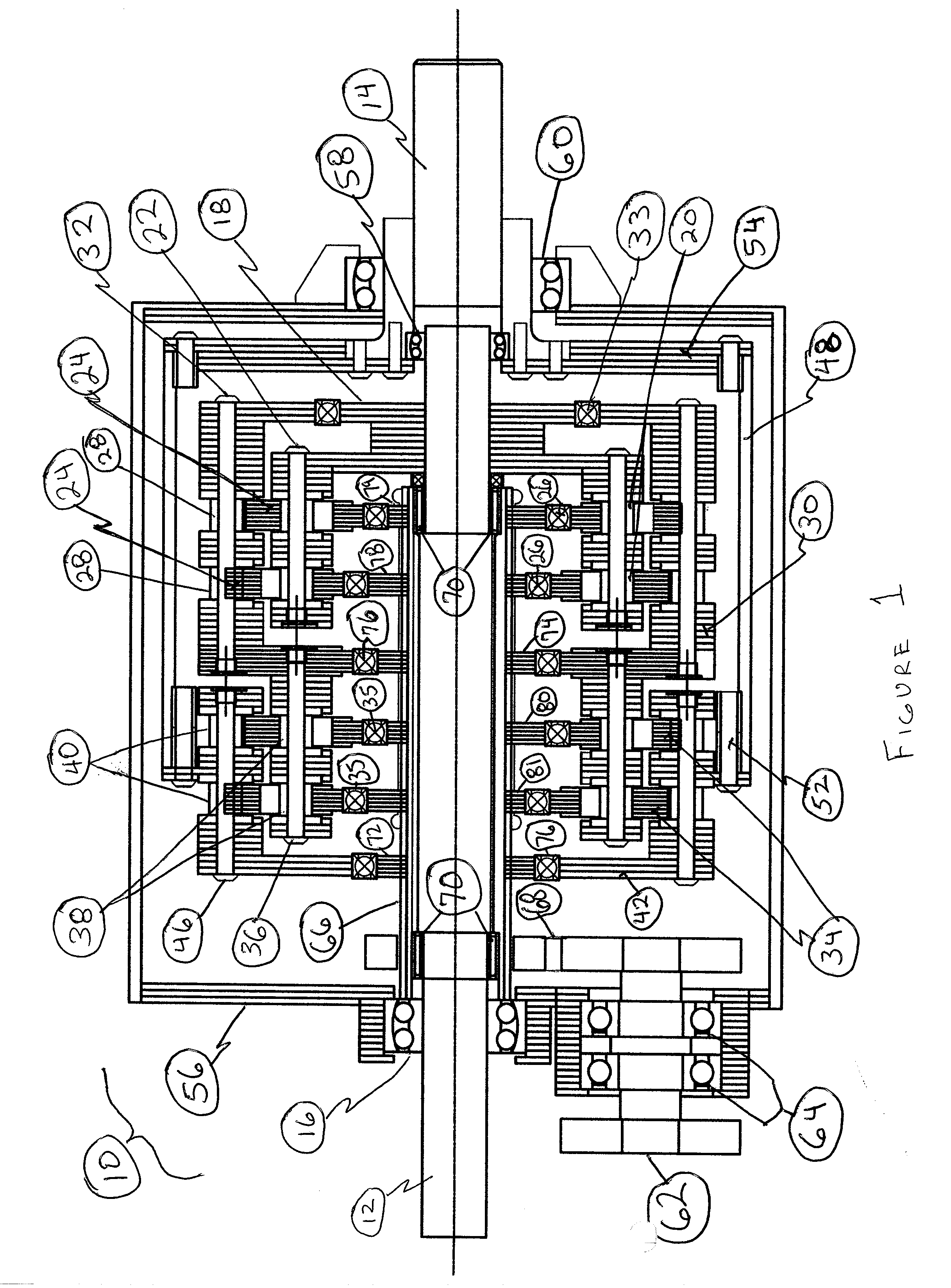
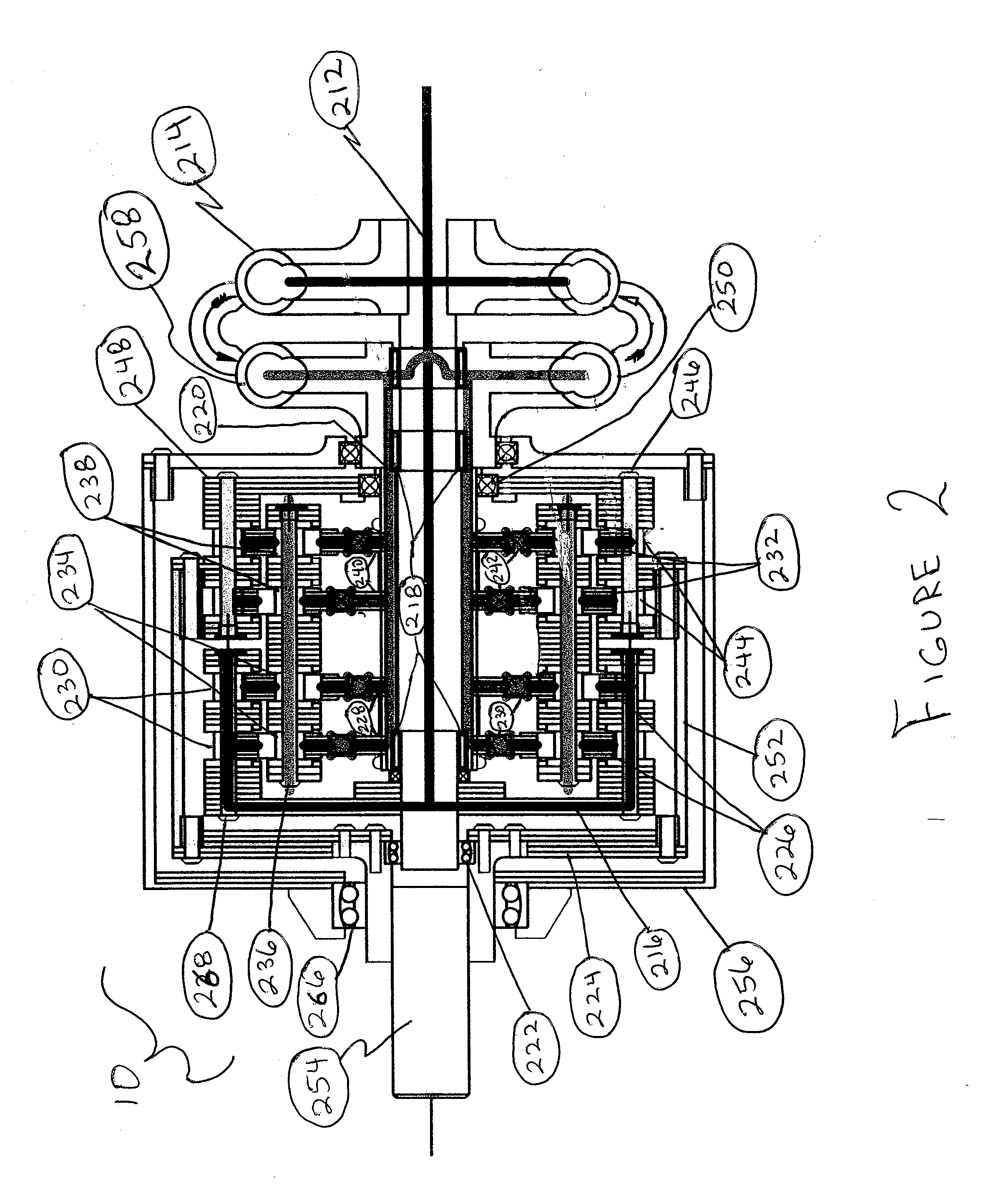
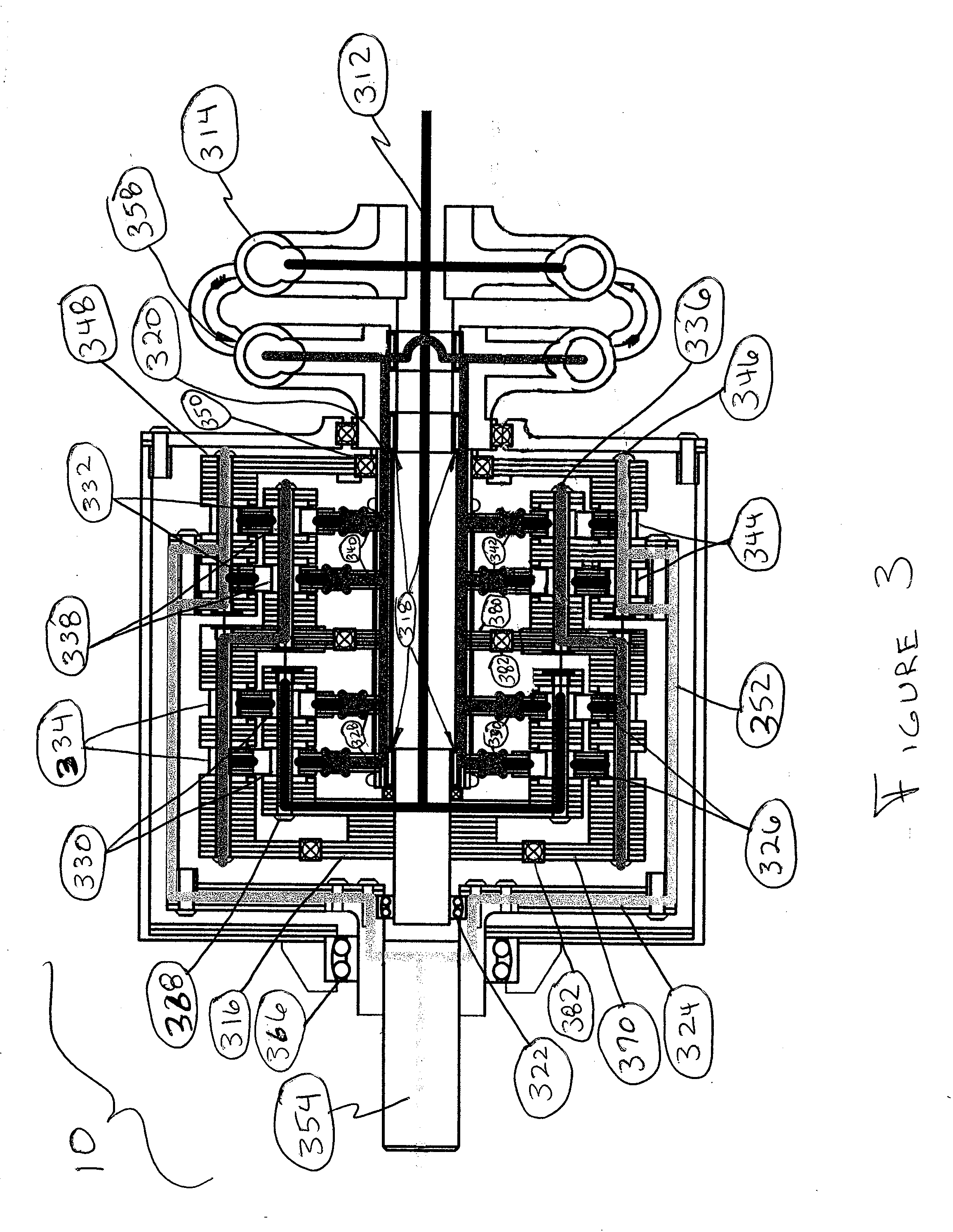
[0036]Referring to FIGS. 1 through 4, a device for continuously variable power transmission is disclosed and generally designated by numeral 10. In the preferred embodiment, the primary components of the device are laminated. That is, each component is comprised of a plurality of relatively thin pieces of source material, generally consisting of a metal alloy or some other suitably rigid material, which are individually cut and sandwiched together using affixing or bonding means to form the final primary components. Accordingly, several different source materials may be laminated into a single part or assembly as needed for the particular application. Production by way of lamination greatly reduces both start up time and cost as well as production time and cost without sacrificing strength or quality. Start up time and cost is reduced by eliminating the need for long-lead casting and machining equipment. Correspondingly, production time and cost is reduced by eliminating the need fo...


PUM


Abstract

The present invention is directed toward an apparatus for continuous speed variation of an output member with respect to a primary input member. In particular, the present invention provides a device having an output that rotates at reduced speed and increased torque relative to its prime input through the low friction, rolling engagement of its members, or alternatively, at increased speed and reduced torque for overdrive applications. Furthermore, the speed of the output member may be varied continuously and infinitely between the apparatus's lowest and highest ratio via a secondary input member and its low friction, rolling engagement with the device's members.

Description

BACKGROUND OF THE INVENTION[0001]1. Field of the Invention[0002]The present invention is directed toward an apparatus for continuous speed variation of an output member with respect to a prime input member. In particular, the present invention provides a device having an output that rotates at reduced speed and increased torque relative to its prime input through the low friction, rolling engagement of its members, or alternatively, at increased speed and reduced torque for overdrive applications. Furthermore, the speed of the output member may be varied continuously and infinitely between the apparatus's lowest and highest ratio via a secondary input member and its low friction, rolling engagement with the device's members.[0003]2. Background Information[0004]The ability to vary the power between an input and output shaft is vital to industries and economies throughout the world. Industries dependent on variable power transmission range from energy exploration and power generation ...

Claims


Application Information

Patent Timeline
Patent Type & Authority Applications(United States)
IPC IPC(8): F16H13/00F16H15/04F16H57/00
CPCF16H47/04F16H3/72
Inventor JONES, DAN
Owner EPI ENERGY LTD A TEXAS
Why Eureka
Try Eureka