
Electric power steering

a technology of electric power steering and steering wheel, which is applied in the direction of electrical steering, electric motor speed/torque regulation, transportation and packaging, etc., can solve the problems of system immediate stop, steering feeling deterioration, and system reliability declin

Inactive Publication Date: 2015-11-03
JTEKT CORP
View PDF20 Cites 2 Cited by
  • Summary
  • Abstract
  • Description
  • Claims
  • Application Information

AI Technical Summary

Benefits of technology

This configuration maintains system reliability, provides an appropriate steering feel based on vehicle conditions, and prevents regenerative brake-induced deterioration, while allowing for flexible installation and continued operation even with phase energization issues.

Problems solved by technology

However, as in the case of the above related examples, when the output characteristic of a single electric motor is frequently varied on the basis of the running condition of a vehicle, components may be degraded because of heat and vibrations of the motor due to a steep torque variation to thereby lead to a decrease in the reliability of the system, and, in some cases, it is conceivable that a steering feeling deteriorates.
In addition, because a single electric motor is controlled, there is a problem that, when there occurs poor energization in any one of the phases (any one of U, V and W phases) of the electric motor due to a break in a power supply line, a contact failure of a driving circuit, or the like, the system should be immediately stopped.
On the other hand, when two electric motors having different output characteristics are arranged at different portions of a steering system from a steering wheel of a vehicle to steered wheels, the portions at which the two electric motors are installed are different, so a steering feeling may include a feeling of strangeness at the time of changing between the two electric motors.
Other than the above, space for installing the two electric motors is required, so the flexibility of installation problematically reduces.

Method used


Image

  • Electric power steering
  • Electric power steering
  • Electric power steering

Examples


Embodiment Construction

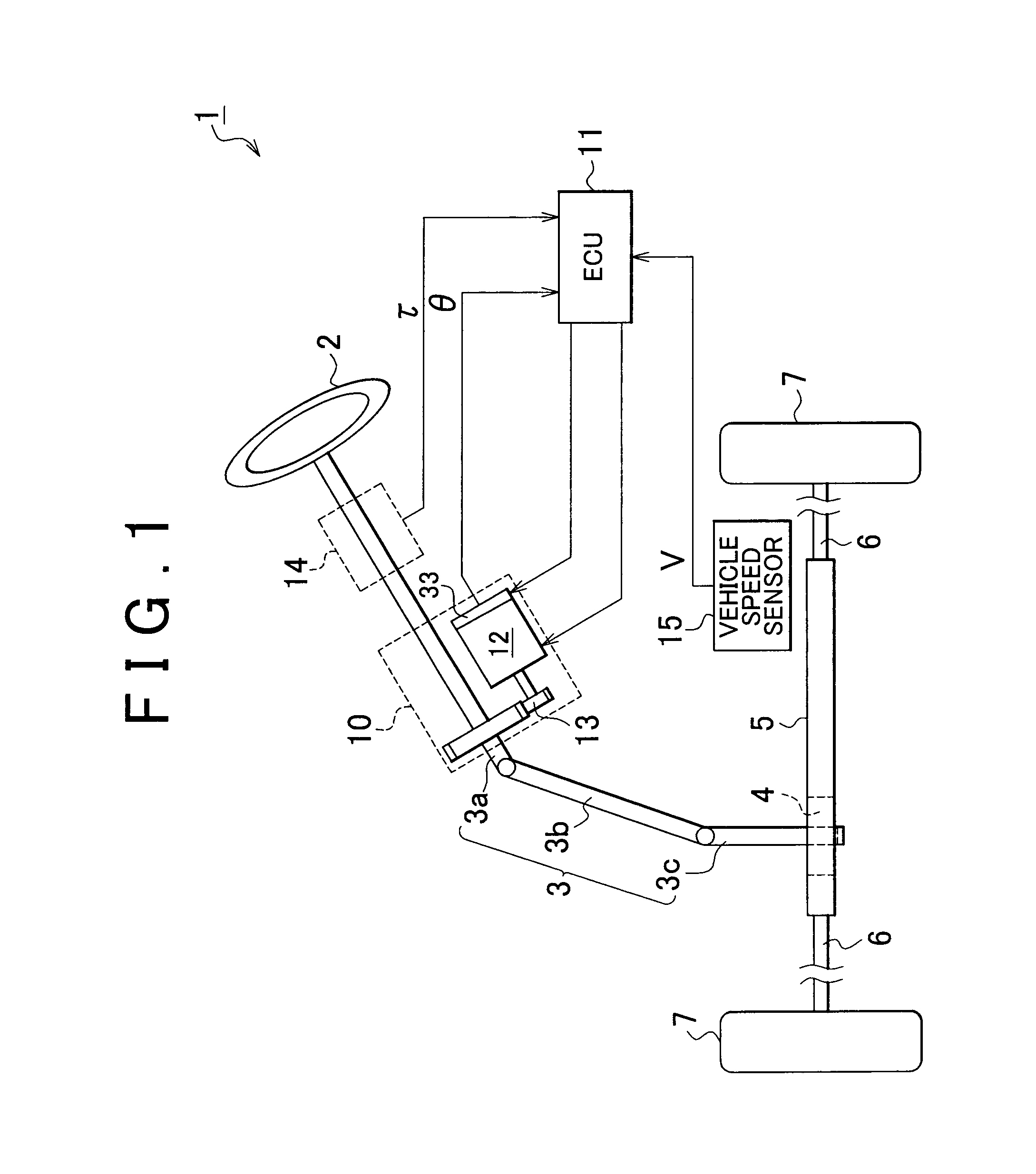
[0033]Hereinafter, a columnar type electric power steering (hereinafter, referred to as EPS) according to a specific embodiment of the invention will be described with reference to the accompanying drawings. As shown in FIG. 1, in the EPS 1 according to the present embodiment, a steering shaft 3 is coupled to a rack shaft 5 via a rack-and-pinion mechanism 4. A steering wheel 2 is fixed to the steering shaft 3. Then, the rotation of the steering shaft 3 resulting from steering operation is converted to reciprocating linear motion of the rack shaft 5 by the rack-and-pinion mechanism 4. Note that the steering shaft 3 according to the present embodiment is formed by coupling a column shaft 3a, an intermediate shaft 3b and a pinion shaft 3c. Then, the reciprocating linear motion of the rack shaft 5 resulting from the rotation of the steering shaft 3 is transmitted to knuckles (not shown) via tie rods 6 coupled to both ends of the rack shaft 5 to thereby vary the turning angle of steered ...


PUM


Abstract

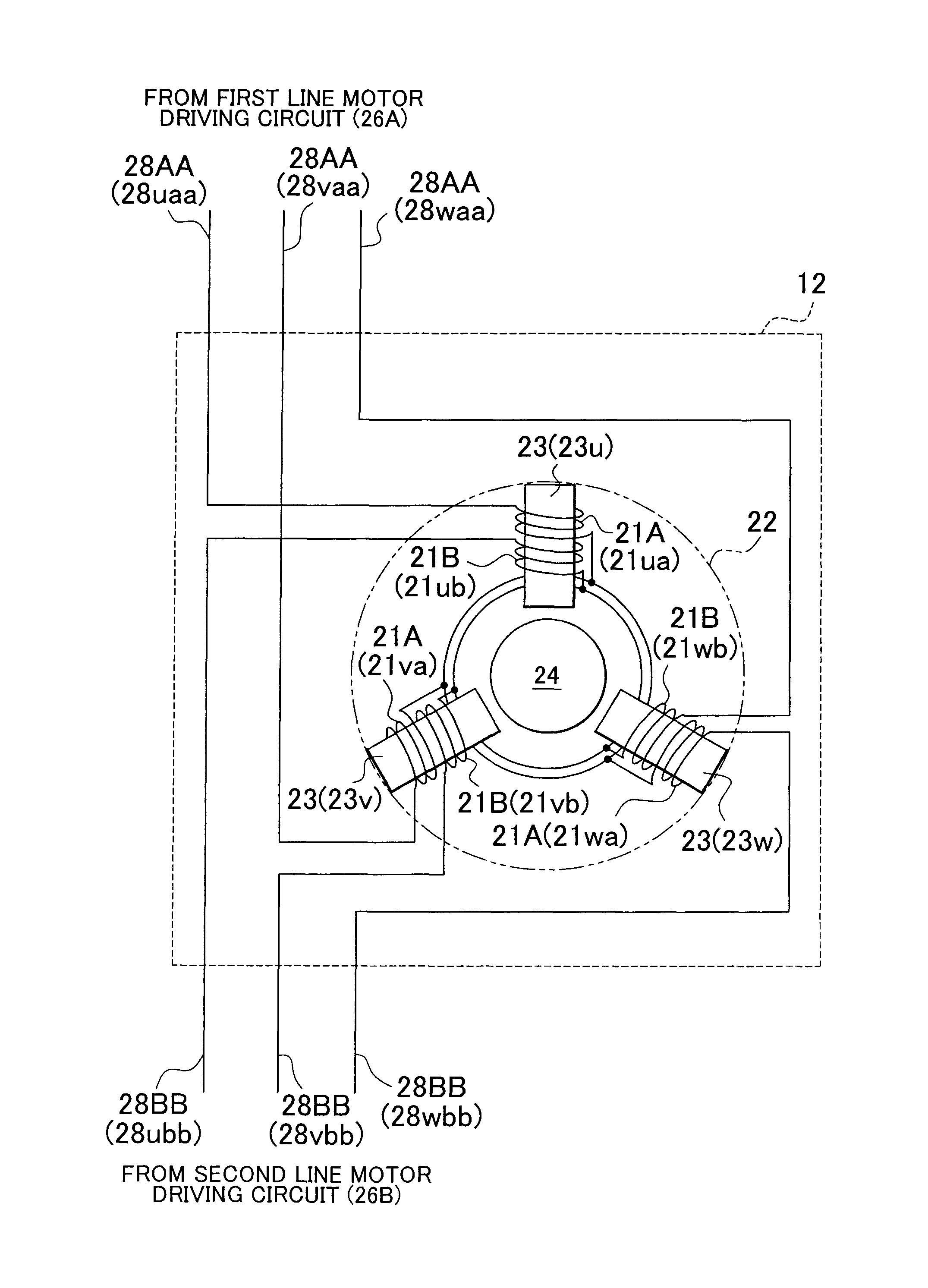
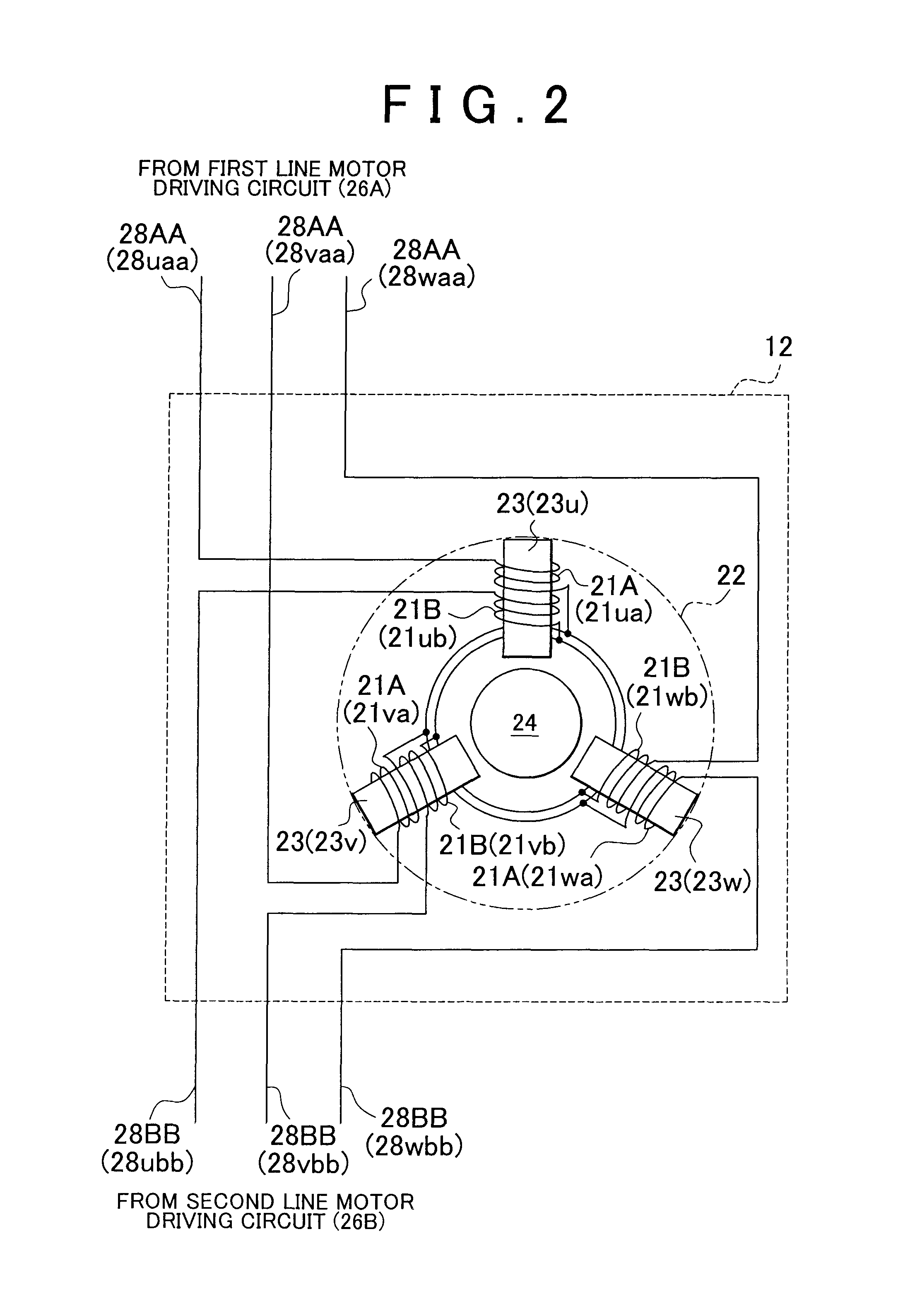
A steering force assisting device that includes an electric motor and includes independent two sets of motor driving circuit and control unit, and the electric motor includes coils having the same polarity and different motor characteristics, the coils being wound around each of teeth of a stator of the electric motor. The motor characteristics are a high speed / low torque characteristic and a low speed / high torque characteristic, and may be selected on the basis of the running condition of a vehicle.

Description

BACKGROUND OF THE INVENTION[0001]1. Field of the Invention[0002]The invention relates to an electric power steering.[0003]2. Description of Related Art[0004]In an existing art, an electric power steering (EPS) controls an electric motor so that steering assist force has an assist characteristic based on the running condition of a vehicle.[0005]For example, a method of controlling the electric motor includes field-weakening control. Field-weakening control is executed only when the vehicle speed is lower than a predetermined value, and is not executed when the vehicle speed is higher than or equal to the predetermined value (for example, see Japanese Patent Application Publication No. 2008-068769 (JP-A-2008-068769)). By so doing, the linearity of the motor characteristic is maintained against steering during running of the vehicle, and motor output according to a command value may be obtained. Therefore, a steering feeling during running improves. On the other hand, field-weakening c...

Claims


Application Information

Patent Timeline
Patent Type & Authority Patents(United States)
IPC IPC(8): B62D5/04H02P29/02H02P5/747H02P25/22
CPCB62D5/04B62D5/0403B62D5/046B62D5/0484H02P5/747H02P25/22H02P29/022H02P29/032
Inventor SUZUKI
Owner JTEKT CORP
Learn More