High performance neutron detector with near zero gamma cross talk

a neutron detector and high-efficiency technology, applied in the field of gamma and neutron detection systems, can solve the problems of helium-3 being a natural resource with a very limited supply, producing much less light, and too many false positive alarms, so as to reduce the manufacturing cost, simplify the manufacturing process of the detector, and increase the light transmission

Inactive Publication Date: 2012-12-11
EMR RESOURCES +2
View PDF113 Cites 12 Cited by
  • Summary
  • Abstract
  • Description
  • Claims
  • Application Information

AI Technical Summary

Benefits of technology

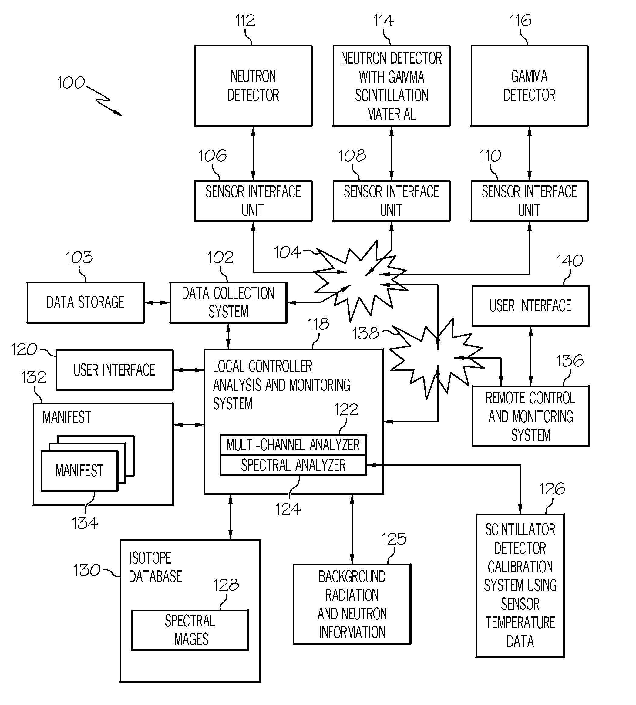
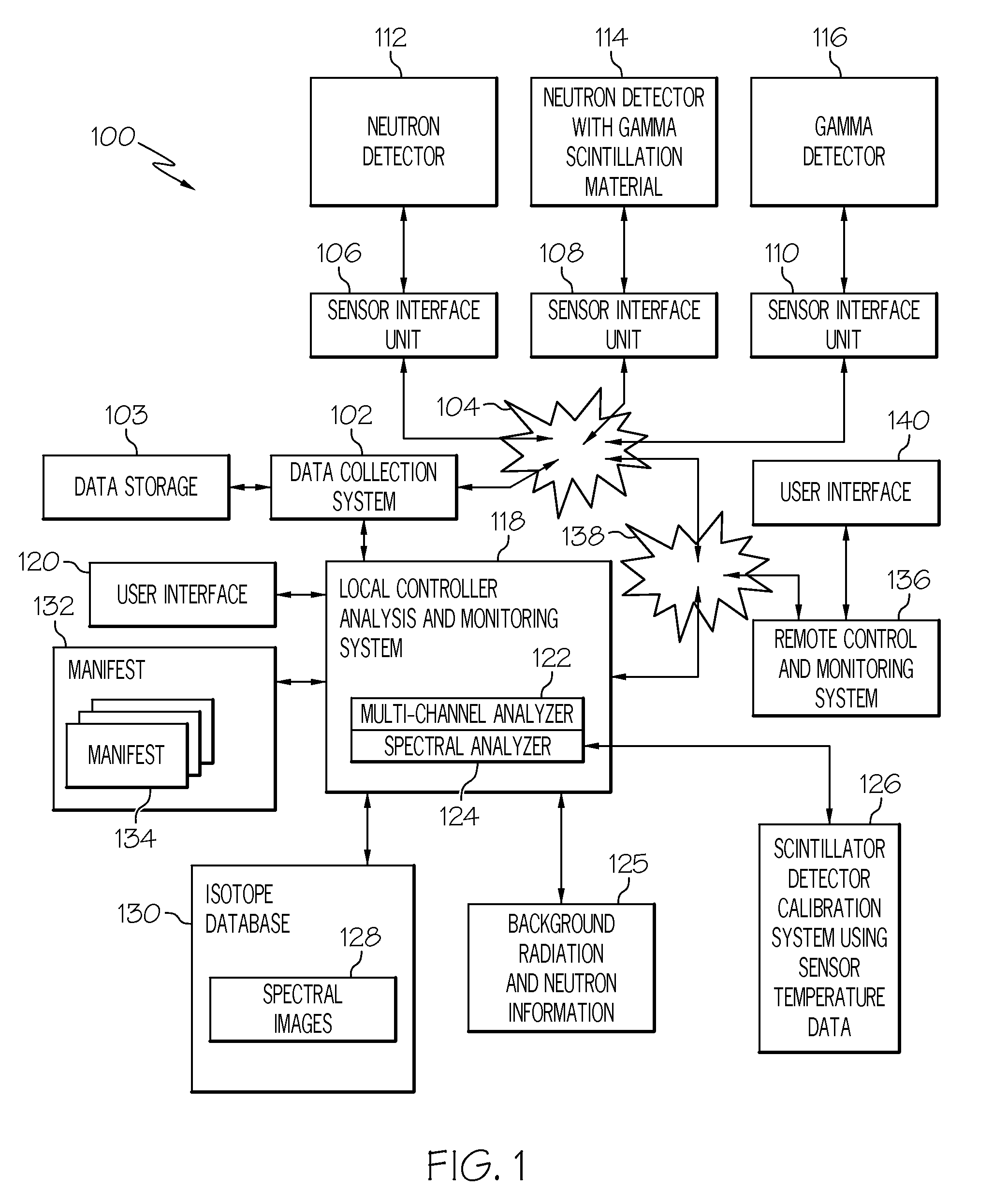
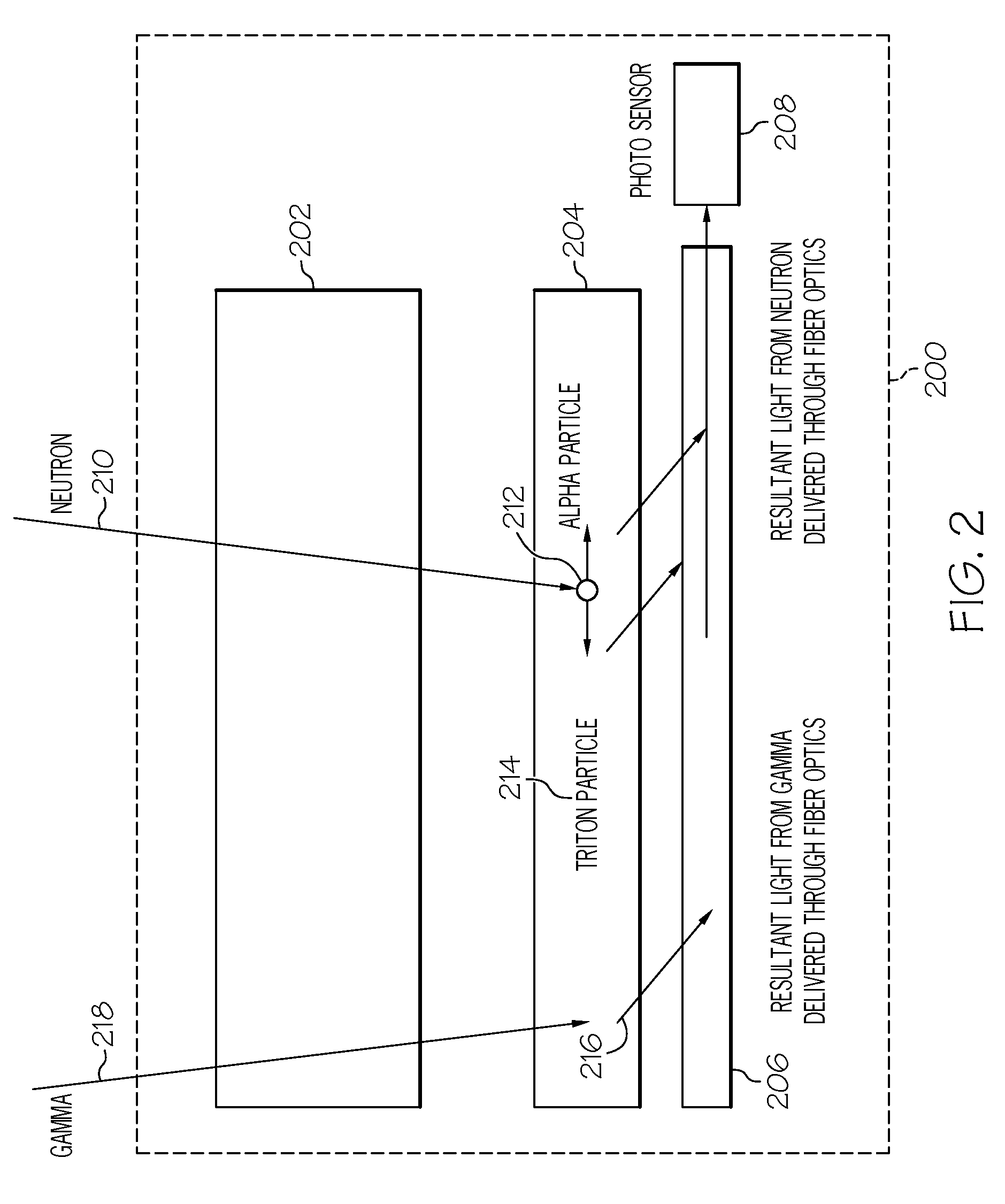
[0015]According to one embodiment, a thermal neutron detector comprises one or more layers of 6LiF mixed in a binder medium with a scintillator material, that are optically coupled to one or more fiber optic light guide media. These optical fibers have a tapered portion extending from one or both ends of said layers to guide the light to a narrowed section. The narrowed section is coupled to a photosensor. A photosensor is coupled to a pre-amp circuit designed to drive the detector signal processing rate close to the decay time of the scintillator material. This enables pulses to be delivered without distortion to a set of electronics that performs analog to digital conversion.
[0017]In another embodiment, the moderator material for the thermal neutron detector system is designed around the thermal neutron detector, and moderator material is not used within the mixture of each detector layer or between detector layers. This structure provides a designed level of moderator interaction with the neutrons before they are introduced to the thermal neutron detector comprising one or more detector layers. Each of the thermal neutron detector layers has an efficiency level for the detection of thermal neutrons. The multiple layers act to increase the detector efficiency. The elimination of moderator materials within the detector layers and / or between the detector layers reduces neutron absorption and increases the number of thermal neutrons available for detection.
[0020]According to one embodiment, staggered multiple layers of optical fiber strands and detector materials can be sandwiched together, where a first set of parallel fiber strands in a first fiber layer are disposed on top of the middle detector material layer and which is disposed on top of a second set of parallel fiber strands in a second fiber layer. The first set of parallel fiber strands is arranged in a staggered orientation relative to the second set of parallel fiber strands. By staggering the two sets of parallel fiber layers by a portion of the diameter of a fiber (such as by one half of the diameter of a fiber), it locates the sandwiched parallel fibers closer together (with the detector material in between) and thereby more likely to couple light photons into the fibers when neutrons interact with the detection materials.
[0022]A protective covering is applied to the detector to eliminate light intrusion into the detector area. Thermistors may be applied to monitor the operating temperature of the detector components to enable automated or manual calibration of the detector output signals.
[0023]A light shield is applied to the outer shell of the detector layers to eliminate outside light interference by using an opaque shrink wrap as a light shield around the detector area up to and or covering a portion of the photosensor. Another method for light shielding could be an opaque covering applied as a liquid that dries onto the detector and acts as a light shield around the detector area up to and / or covering a portion of the photosensor.
[0026]According to another embodiment, a solid state photomultiplier is located adjacent to, and optically coupled with, a scintillation detector layer. The binder material can be selected to be clear and translucent, allowing more light transmission. The light emitted from the detector layer is directly detected by the solid state photomultiplier, which then delivers electrical signal to an amplifier circuit and thereby to a digital signal processing circuit. This configuration of a detector system advantageously eliminates using wavelength shifting optical fibers to guide light out of the scintillation detector layer, which reduces manufacturing cost and simplifies the manufacturing process for the detector.

Problems solved by technology

One problem with conventional neutron detectors based on helium-3 is that helium-3 is a natural resource with a very limited supply.
Unfortunately, these levels of gamma rejection in conventional neutron detectors can result in too many false positive alarms, indicating that a neutron particle has been detected when in reality a gamma particle was detected.
One problem with these types of detectors is that they produce much less light per neutron collision event and require much more gain in a photomultiplier tube (PMT).
These types of devices also have increased gamma ray sensitivity and use analog techniques to separate gamma from neutron collision events, which typically result in gamma pulse rejection rates of 4 in ten thousand, leaving an unsatisfactory rate of gamma false positives.
However, the analog pulse shape differentiation methods available were technically insufficient to correct the gamma interference.
In addition, the use of moderator material within the 6LiZnS(Ag) detector mixture or between the 6LiAnS(Ag) detector layers causes a loss of thermal neutrons due to absorption by the moderator material reducing the number of available thermal neutrons for detection.
However, the analog pulse shape differentiation methods available were insufficient to correct the gamma interference.
Current attempts at the detection of special nuclear materials such as highly enriched uranium have had difficulties with the low number of neutrons and the ability to shield low gamma energy that are generated from these materials.
Therefore, conventional detectors do not adequately detect special nuclear materials.

Method used


Image

  • High performance neutron detector with near zero gamma cross talk
  • High performance neutron detector with near zero gamma cross talk
  • High performance neutron detector with near zero gamma cross talk

Examples


Embodiment Construction

[0050]As required, detailed embodiments of the present invention are disclosed herein; however, it is to be understood that the disclosed embodiments are merely examples of the invention, which can be embodied in various forms. Therefore, specific structural and functional details disclosed herein are not to be interpreted as limiting, but merely as a basis for the claims and as a representative basis for teaching one skilled in the art to variously employ the present invention in virtually any appropriately detailed structure and function. Further, the terms and phrases used herein are not intended to be limiting; but rather, to provide an understandable description of the invention.

[0051]The terms “a” or “an”, as used herein, are defined as one or more than one. The term plurality, as used herein, is defined as two or more than two. The term another, as used herein, is defined as at least a second or more. The terms including and / or having, as used herein, are defined as comprisin...


PUM


Abstract

A scintillator system is provided to detect the presence of fissile material and radioactive material. One or more neutron detectors include scintillator material, and are optically coupled to one or more wavelength shifting fiber optic light guide media that extend from the scintillator material to guide light from the scintillator material to a photosensor. An electrical output of the photosensor is connected to an input of a pre-amp circuit designed to provide an optimum pulse shape for each of neutron pulses and gamma pulses in the detector signals. Scintillator material as neutron detector elements can be spatially distributed with interposed moderator material. Individual neutron detectors can be spatially distributed with interposed moderator material. Detectors and moderators can be arranged in a V-shape or a corrugated configuration.

Description

CROSS-REFERENCE TO RELATED APPLICATIONS[0001]This application claims priority from prior provisional application 61 / 208,492 filed on Feb. 25, 2009. This application claims priority from prior provisional application 61 / 209,194 filed on Mar. 4, 2009. This application claims priority from prior provisional application 61 / 210,075 filed on Mar. 13, 2009. This application claims priority from prior provisional application 61 / 210,122 filed on Mar. 13, 2009. This application claims priority from prior provisional application 61 / 210,234 filed on Mar. 16, 2009. This application claims priority from prior provisional application 61 / 210,238 filed on Mar. 16, 2009. This application claims priority from prior provisional application 61 / 211,629 filed on Apr. 1, 2009. This application claims priority from prior provisional application 61 / 219,111 filed on Jun. 22, 2009. This application claims priority from prior provisional application 61 / 231,805 filed on Aug. 6, 2009. This application claims prio...

Claims


Application Information

Patent Timeline
Patent Type & Authority Patents(United States)
IPC IPC(8): G01T3/00
CPCG01T3/06
Inventor FRANK, DAVID L.
Owner EMR RESOURCES
Why Eureka
Try Eureka