Method and device for producing bent spring elements

a technology of bent springs and components, applied in the direction of manufacturing tools, vehicle maintenance, vehicle cleaning, etc., can solve the problems of large length differences, inaccuracy of bending, increased wear, etc., and achieve the effects of increasing wear, increasing speed, and high acceleration

Inactive Publication Date: 2012-12-18
ROBERT BOSCH GMBH
View PDF28 Cites 21 Cited by
  • Summary
  • Abstract
  • Description
  • Claims
  • Application Information

AI Technical Summary

Benefits of technology

[0005]According to the invention, the feed of the spring steel strip is not interrupted. This is possible in that the cutting tools can be moved in the longitudinal direction of the spring steel strip in a numerically controlled fashion and are synchronized with the feed movement of the spring steel strip during the cutting process. The uniform feed speed results in a likewise uniform bending profile in the bending unit, which has a positive effect on the properties of the bent spring elements. In contrast, the known devices operate with a start-stop system with very different speeds and high levels of acceleration during a feed and bending process, in particular if large unit quantities are to be produced per unit time. The intermittent feed loads the components and leads to increased wear. As a result of the continuous feed movement, better interaction of the drive motors with one another takes place, so that less wear occurs and a higher output is possible. In addition, it is possible to dispense with so-called trigger holes in the spring steel strip for the control of the process. Said trigger holes can lead to large length differences and bending inaccuracies.
[0006]In a device for carrying out the method, the cutting tools are arranged so as to be adjustable relative to the spring steel strip in the longitudinal direction of the feed movement of said spring steel strip, with the adjusting movement of said cutting tools being synchronized with the feed movement of the spring steel strip during the cutting process by means of an electronic control unit. Here, it is possible for the cutting tools together with the cutting unit to be adjustable relative to the spring steel strip in the longitudinal direction of the feed movement of said spring steel strip, or for the cutting tools to be arranged in a stationary housing of the cutting unit, in which said cutting tools are adjustable relative to the housing and relative to the spring steel strip in the longitudinal direction of the feed movement of said spring steel strip. The second alternative is simpler to implement, and the cutting tools can be activated in a more precise fashion.
[0007]A roller guide serves to guide the spring steel strip between the bending unit and the cutting tools, the rollers of which roller guide can be pneumatically adjusted onto the spring steel strip. It is also expediently possible for some guide rollers in the region of the cutting tools to be varied in terms of their position with respect to one another in the longitudinal direction in such a way that their spacings to one another are increased or decreased as a function of the movement of the cutting tools in the longitudinal direction. The adjustment of the cutting tools in the longitudinal direction of the spring strip results in different spacings between the bending unit and the cutting tools. It is therefore advantageous if some guide rollers can adapt to said different spacing and can be distributed over the spacing without excessive gaps.
[0008]In order to be able to produce many different lengths and bends, it is advantageous to arrange the cutting tools in a stationary housing in which a defined zero point position is determined for the cutting tools which move in the longitudinal position. In order to be able to set the bending unit to the respective type of spring elements at the zero point of the cutting unit, it is expedient to design said bending unit to likewise be adjustable in the longitudinal direction. The adjustment to a spring element type can take place manually when setting up the device. Said bending unit can advantageously also be adjusted in a motor-driven fashion by means of a spindle drive. It is thereby possible for the adjustment to be incorporated into an automatic set-up process. It is also expedient to adjust not only the bending unit in the longitudinal direction but also to combine the bending unit with the feed unit and at least one NC measuring wheel into a structural unit which is adjustable in the longitudinal direction.
[0010]For the extraction of the finished spring elements, it is advantageous for the cutting unit to be adjoined by an ejection device which is driven and which can be activated by means of the electronic control unit. Here, it is expedient for the spring element which is to be cut off to extend a short distance beyond the cutting tools in the feed direction, so that it can be easily gripped by the ejection device.

Problems solved by technology

The intermittent feed loads the components and leads to increased wear.
Said trigger holes can lead to large length differences and bending inaccuracies.

Method used


Image

  • Method and device for producing bent spring elements
  • Method and device for producing bent spring elements
  • Method and device for producing bent spring elements

Examples


Embodiment Construction

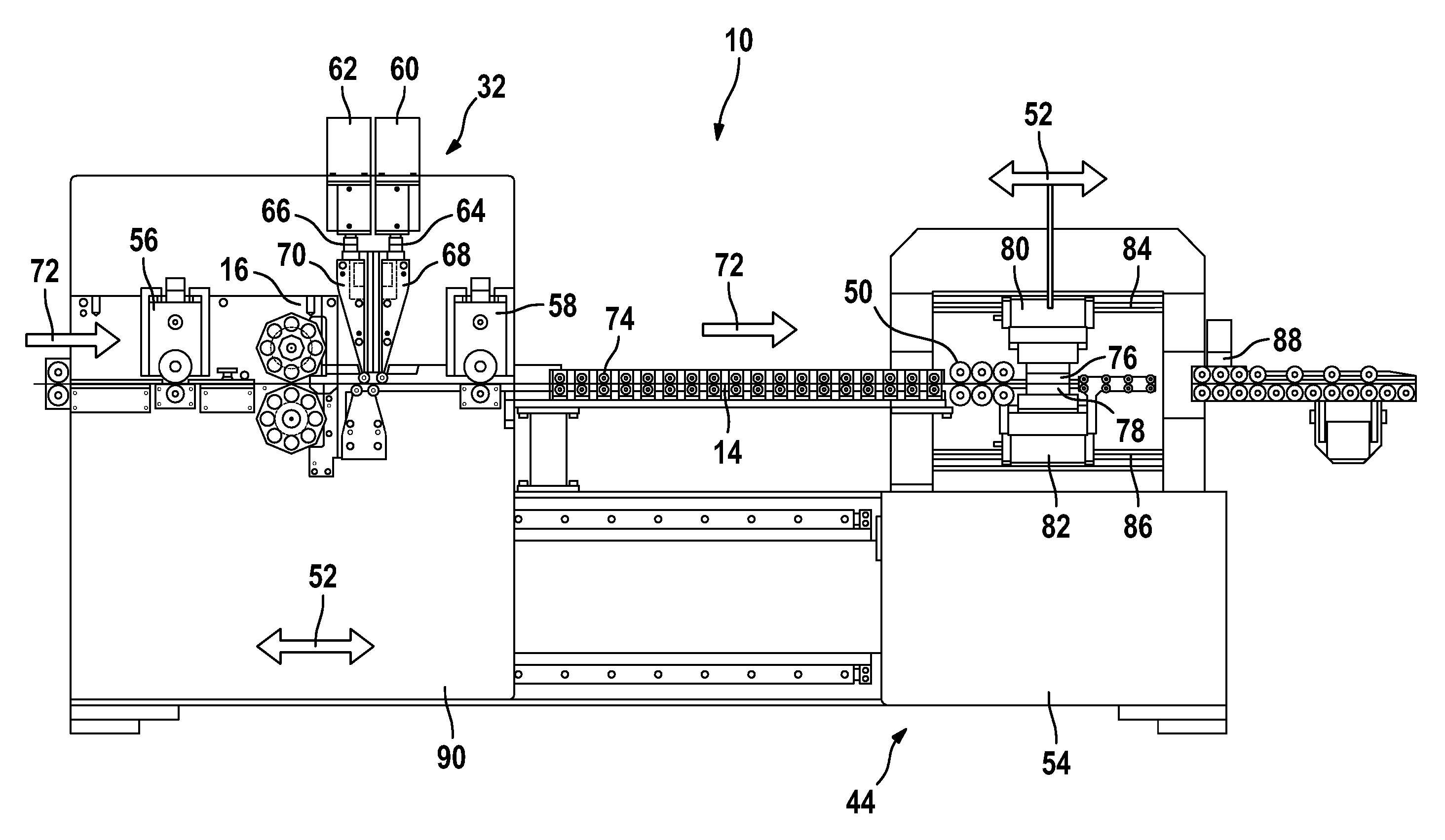
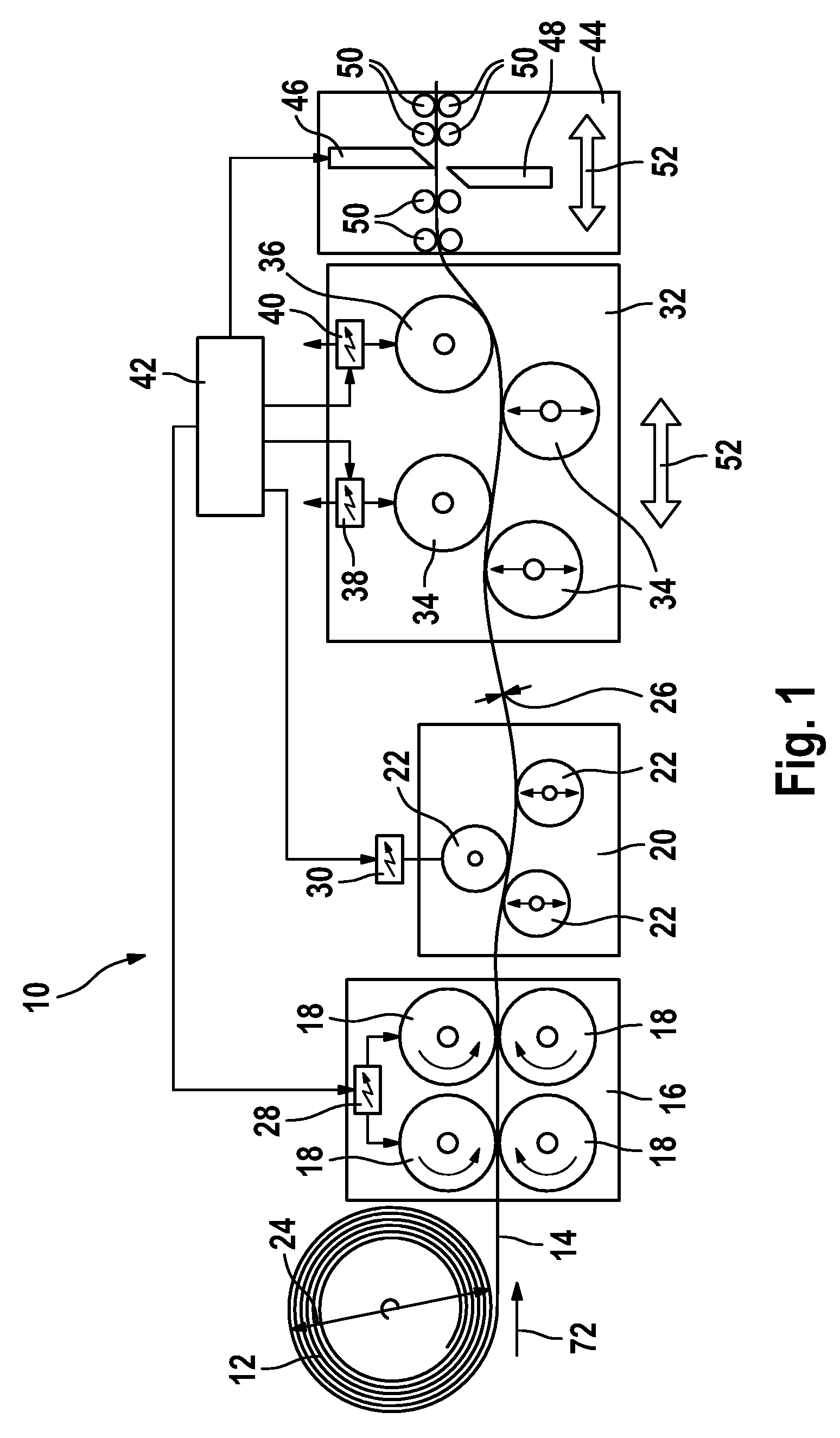
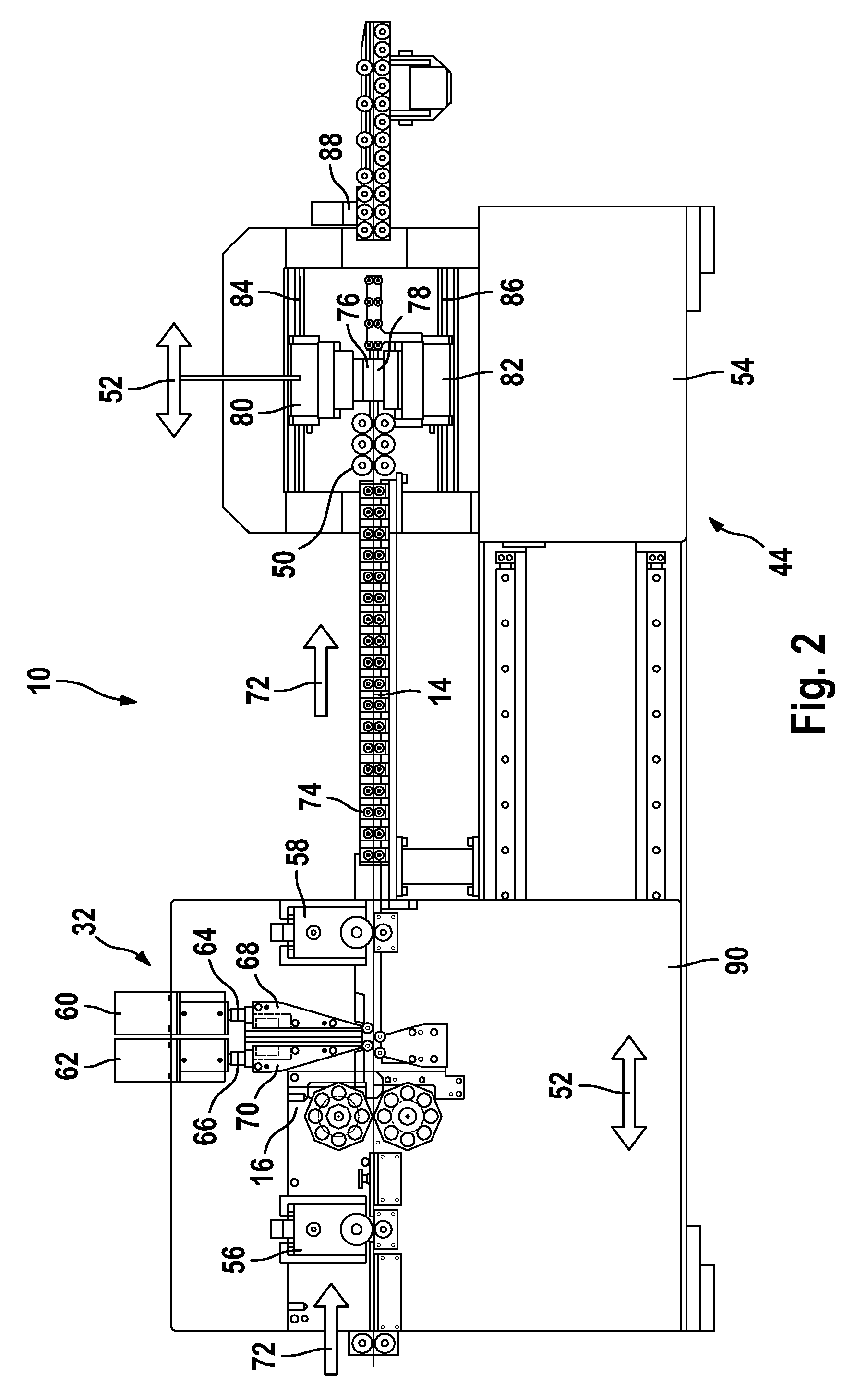
[0016]A device 10 according to the invention comprises substantially a feed unit 16, a bending unit 32 and a cutting unit 44. The feed unit 16 has at least two feed rollers 18 which are situated opposite one another and between which a spring steel strip 14 is guided through. The feed rollers 18 which are adjusted and driven by means of an actuating device 28 feed the spring steel strip 14 from a supply roll 12 to the bending unit 32. In the latter, three bending rollers 34 are arranged with respect to one another in such a way that the spring steel strip 14 is bent with a predefined curvature. At least one of the bending rollers 34 can be adjusted transversely with respect to the longitudinal direction 52 of the spring steel strip 14 by means of an actuating device 38, so that the bend curvature can be varied. In the feed direction 72 of the spring steel strip 14, the three bending rollers 34 are followed by a reverse bending roller 36 which can be adjusted transversely with respec...


PUM

PropertyMeasurementUnit
thicknessaaaaaaaaaa
lengthaaaaaaaaaa
feed rateaaaaaaaaaa

Abstract

The invention is based on a method of producing bent spring elements from a spring steel strip (14), wherein a feed unit (16) delivers the spring steel strip (14) from a supply roll (12) to a bending unit (32) having at least three bending rollers (34) and a reverse bending roller (36), of which at least one bending roller (34) and the reverse bending roller (36) can be adjusted transversely to the spring steel strip (14) by bending motors (60, 62), and wherein a cutting-off unit (44) adjoins the bending unit (32), said cutting-off unit (44) cutting off the spring steel strip (14) into individual spring elements by means of cutting-off tools (46, 48; 76, 78). It is proposed that the cutting-off tools (46, 48; 76, 78) be movable in the longitudinal direction of the spring steel strip (14) in a numerically controlled manner and that they be synchronized with the feed movement of the spring steel strip (14) during the cutting-off operation.

Description

BACKGROUND OF THE INVENTION[0001]The invention is based on a method and a device for producing bent spring elements.[0002]DE 198 16 609 A1 discloses a method and a device for producing flat-beam wipers for vehicles with bent spring elements, so-called flat beams. Said flat beams form the support element of the wiper blade and preferably have a material thickness which varies over the length. Said flat beams are produced from a tempered spring steel strip which is supplied by two feed rollers, which are arranged in a pair, via guide rollers to a bending unit at a continuous feed rate. The bending unit comprises a cutting unit which serves to cut the individual support elements from one another after they are bent. The continuous feed movement is briefly interrupted during the cutting process.[0003]In the bending unit, the spring steel strip is bent firstly in the one direction by three points of contact and is bent back by a small percentage by a subsequent contact point. The degree ...

Claims


Application Information

Patent Timeline
Patent Type & Authority Patents(United States)
IPC IPC(8): B21F11/00
CPCB21D7/08B21D11/10B21D53/886B23D25/08B23D25/04Y10T29/49609B60S2001/3898B21D53/88
Inventor KLECKNER, JOSEFMAZURKIEWICZ, JULIUSCRIEL, PAUL
Owner ROBERT BOSCH GMBH
Why Eureka
Try Eureka