Mobile external coupling with internal sealing cuff for branch vessel connection

a branch vessel and mobile technology, applied in the field of endoluminal prosthesis or graft having a mobile external coupling, can solve the problems of extended recovery period, high invasiveness, and inability to perform on individuals with fragile health or other contraindicative factors

Active Publication Date: 2012-12-18
MEDTRONIC VASCULAR INC
View PDF34 Cites 56 Cited by
  • Summary
  • Abstract
  • Description
  • Claims
  • Application Information

AI Technical Summary

Problems solved by technology

Such surgery is highly invasive, requires an extended recovery period and, therefore, cannot be performed on individuals in fragile health or with other contraindicative factors.
The use of stent-grafts to internally bypass, within the aorta or flow lumen, the aneurysmal site, is also not without challenges.
As a result, blood leakage is prone to occur into the space between the outer surface of the main aortic stent graft and the surrounding aortic wall between the edge of the graft material surrounding the fenestrations and the adjacent vessel wall.
Similar blood leakage can result from post-implantation migration or movement of the stent-graft causing misalignment between the fenestration(s) and the branch artery(ies), which may also result in impaired flow into the branch artery(ies).
This connection between the branch graft and main graft may be difficult to create effectively in situ and is a site for potential leakage.
Such branch graft extensions are folded or collapsed against the main stent-graft for delivery and require complicated procedures, requiring multiple sleeves and guide wires, to direct the branch extension into the branch vessel and subsequently expand.
Further, in some instances, such branch stent-grafts tend to return to their folded or collapsed configuration, and thus do not provide an unobstructed flow path to the branch vessel.

Method used


Image

  • Mobile external coupling with internal sealing cuff for branch vessel connection
  • Mobile external coupling with internal sealing cuff for branch vessel connection
  • Mobile external coupling with internal sealing cuff for branch vessel connection

Examples


Embodiment Construction

[0033]Specific embodiments are now described with reference to the figures, wherein like reference numbers indicate identical or functionally similar elements. Unless otherwise indicated, for the delivery system the terms “distal” and “proximal” are used in the following description with respect to a position or direction relative to the treating clinician. “Distal” and “distally” are positions distant from or in a direction away from the clinician, and “proximal” and “proximally” are positions near or in a direction toward the clinician. For the stent graft device “proximal” is the portion nearer the heart by way of blood flow path while “distal” is the portion of the stent graft further from the heart by way of blood flow path.

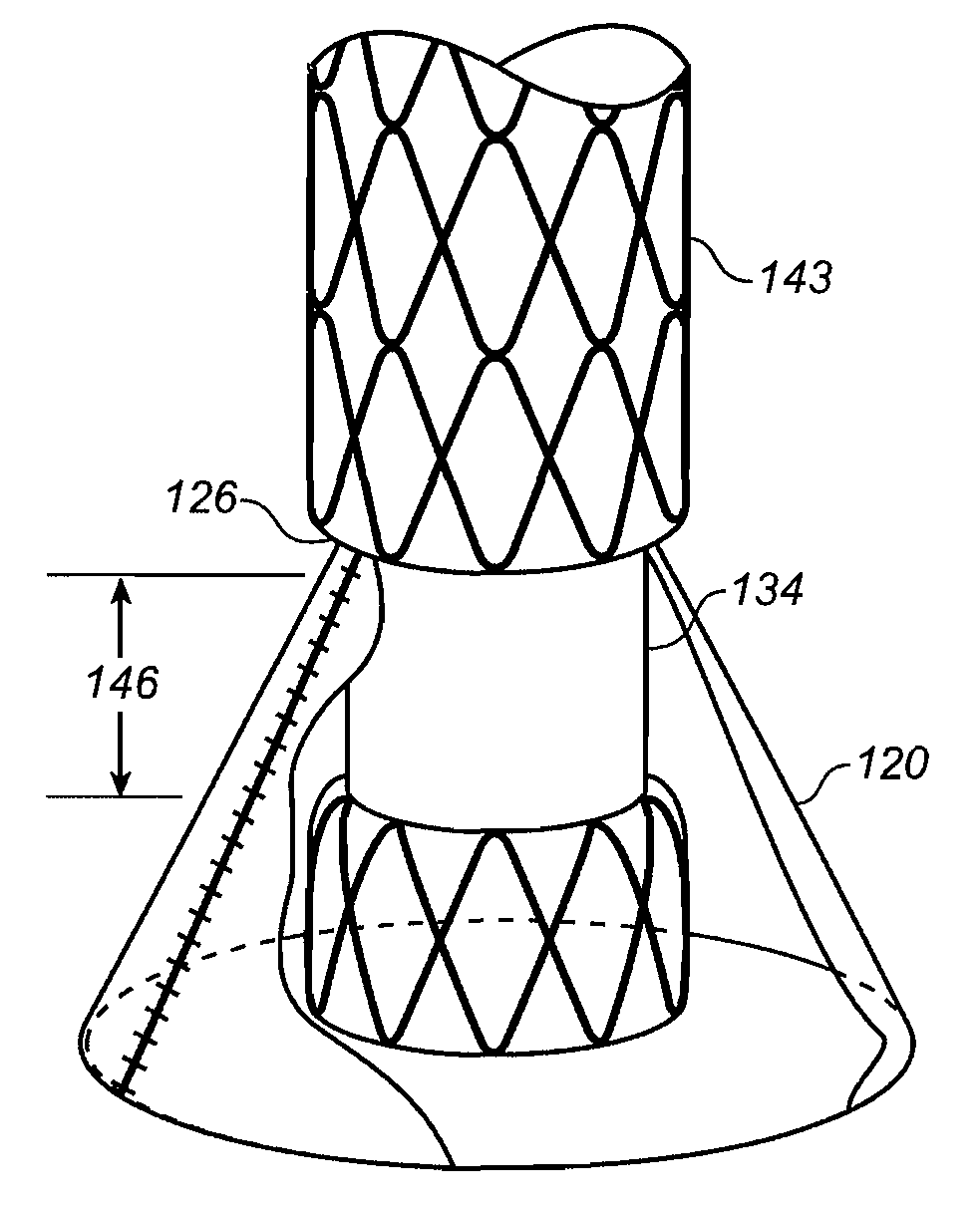
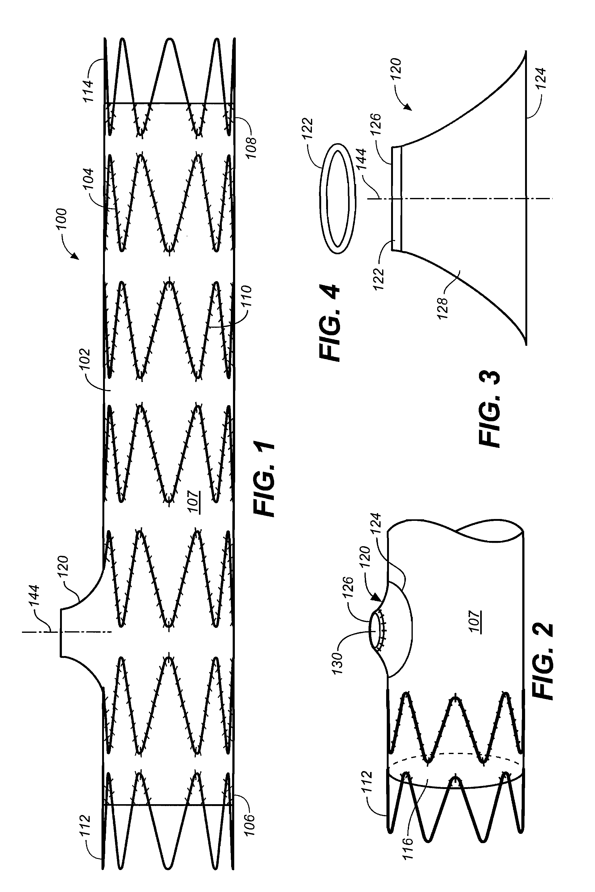
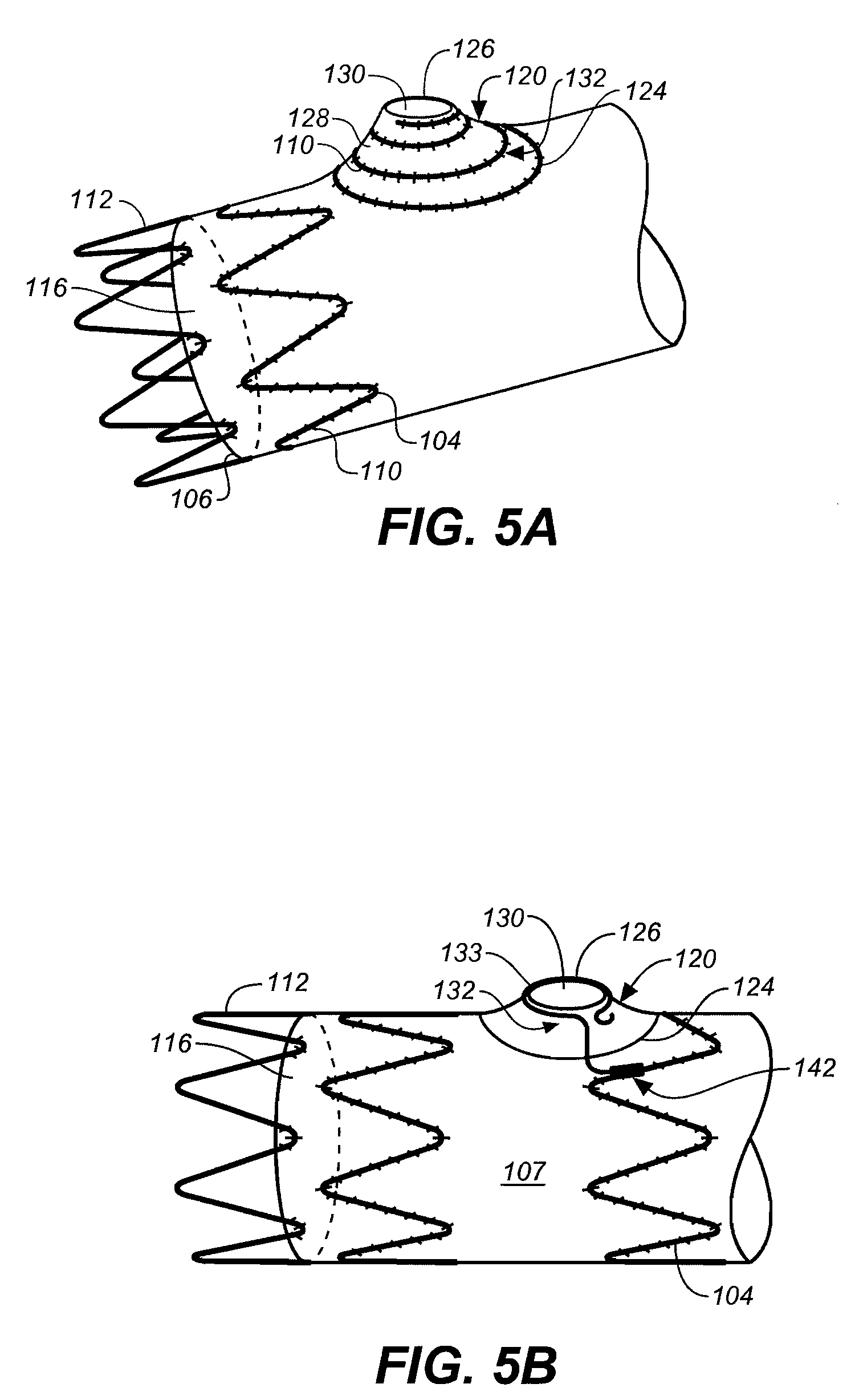
[0034]With reference to FIGS. 1-4, a stent-graft 100 is configured for placement in a vessel such as the aorta. Stent-graft 100 includes graft material 102 coupled to circumferential stents 104. Graft material 102 may be coupled to circumferential stents 104...


PUM


Abstract

An endovascular prosthesis includes a tubular body and a mobile external coupling. The tubular body includes a graft material and stents coupled thereto, a forms a lumen therethrough. The mobile external coupling extends outwardly from the tubular body. The mobile external coupling includes a graft material and is generally frustoconically shaped. The mobile external coupling includes a base coupled to the tubular body, a top spaced from the tubular body, and a coupling lumen disposed between the base and the top, wherein the coupling lumen is in flow communication with the body lumen. A cylindrical sealing cuff of graft material is attached to and extends from the top of the mobile external coupling towards the tubular body within the coupling lumen. The sealing cuff is configured to contact a portion of a branch vessel prosthesis and thereby provides an elongated interference seal between the branch vessel prosthesis and the mobile external coupling.

Description

FIELD OF THE INVENTION[0001]This invention relates generally to endoluminal medical devices and procedures, and more particularly to an endoluminal prosthesis or graft having a mobile external coupling for connecting a main graft to a branch vessel graft.BACKGROUND[0002]Aneurysms and / or dissections may occur in blood vessels, and most typically occur in the aorta and peripheral arteries. Depending on the region of the aorta involved, the aneurysm may extend into areas having vessel bifurcations or segments of the aorta from which smaller “branch” arteries extend. Various types of aortic aneurysms may be classified on the basis of the region of aneurysmal involvement. For example, thoracic aortic aneurysms include aneurysms present in the ascending thoracic aorta, the aortic arch, and branch arteries that emanate therefrom, such as subclavian arteries, and also include aneurysms present in the descending thoracic aorta and branch arteries that emanate therefrom, such as thoracic inte...

Claims


Application Information

Patent Timeline
Patent Type & Authority Patents(United States)
IPC IPC(8): A61F2/06
CPCA61F2/07A61F2002/061A61F2250/006A61F2220/0075A61F2002/075A61F2220/005A61F2220/0058A61F2/89
Inventor BRUSZEWSKI, WALTERMUZSLAY, HEATHJOHNSON, EMILIEBOYLE, KEVINIFTEKHAR, MOHAMMEDROBAINA, SAMUEL
Owner MEDTRONIC VASCULAR INC
Why Eureka
Try Eureka