
Mass-exchange contact device

a contact device and mass exchange technology, applied in the chemical industry, liquid-gas reaction process, combustion air/fuel air treatment, etc., can solve the problems of increasing the hydraulic resistance of the plate, increasing and increasing the speed of the volatile phase change along the column height, so as to reduce the height of the column and the metal content, increasing the reliability and durability of the device operation

Active Publication Date: 2012-12-18
MALETA BOGDAN +1
View PDF7 Cites 4 Cited by
  • Summary
  • Abstract
  • Description
  • Claims
  • Application Information

AI Technical Summary

Benefits of technology

"The present invention aims to improve mass-exchange devices and methods for mass-exchange between a liquid phase component and a volatile phase component. The invention provides an ordered alteration of the concentration of the volatile phase component along the height of the liquid phase layer and a predeterminedly extensive mass-exchange surface in the inventive mass-exchange contact device. The invention also reduces the height of the column and the metal content of the column, and costs of the column, increasing the reliability and durability of device operation. The invention provides a plurality of mass exchange contact devices that can be stacked vertically in a column, and each device is combined with a packing means or a grating and a granular layer of catalytic material. The technical effects of the invention include improved mass-exchange efficiency, reduced height and metal content of the column, increased reliability and durability of device operation, and improved performance and economics of the mass-exchange process."

Problems solved by technology

The disadvantages of the mentioned device are: it's composed of two movable parts; there is a restriction of the opening cross-section of branch pipe for passing gas (steam), as well as a restriction of the ringed holes' opening cross-section for a liquid flow.
These disadvantages increase the plate's hydraulic resistance at the time of gas (steam) passing, and the time of transferring liquid from one plate to another.
A disadvantage of the above-mentioned devices is that the volatile phase changes its speed along the height of the column due to varying the percentage of the volatile phase.
Therefore, the ascending volatile phase flow cannot stably support the liquid phase in a cyclic mode.
Hence, empty zones appear within the structured packing elements, the phases move unevenly, causing low separation efficiency.
This prevents arranging an efficient mass-exchange process with separate movements (i.e. in a cyclic mode) of the phases in the column.
This disadvantage is conditioned by the fact that the packing element creates a resistance to the liquid phase moving along the mass-exchange tray, and a mass-exchange surface is formed only due to barbotage.
The above-mentioned devices have also another disadvantage of stochastic formation of the mass-exchange surface on the trays, while the liquid is intermingled throughout the whole volume of liquid phase.
A shortcoming of the last two patents is that the amount of costly catalyst is high, which makes the devices expensive.
The related art devices also cannot control the speed of chemical reactions, since they don't provide for regulation of the time of introduction of the volatile phase into the column.

Method used


Image

  • Mass-exchange contact device
  • Mass-exchange contact device
  • Mass-exchange contact device

Examples


first embodiment

Parent

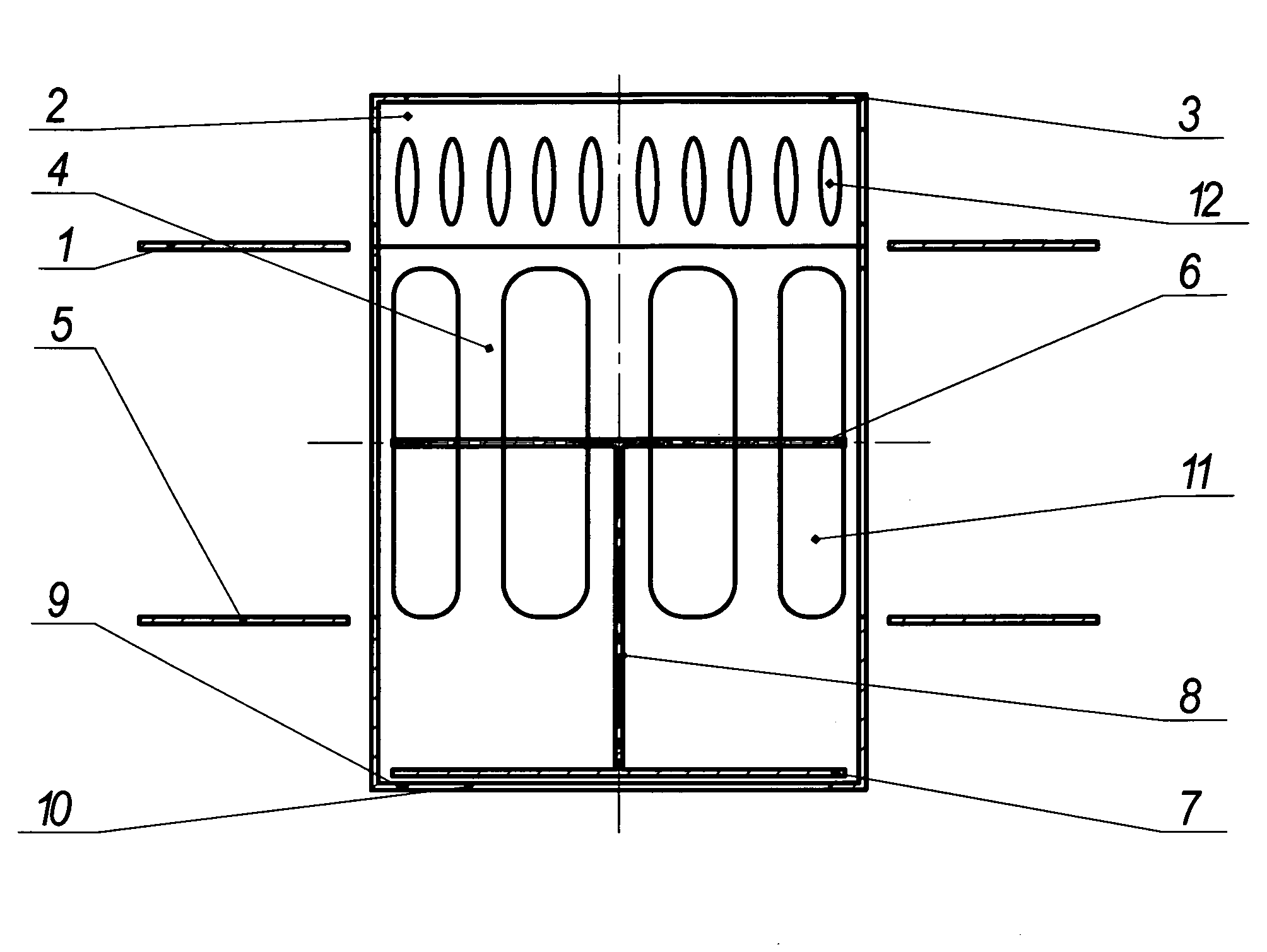
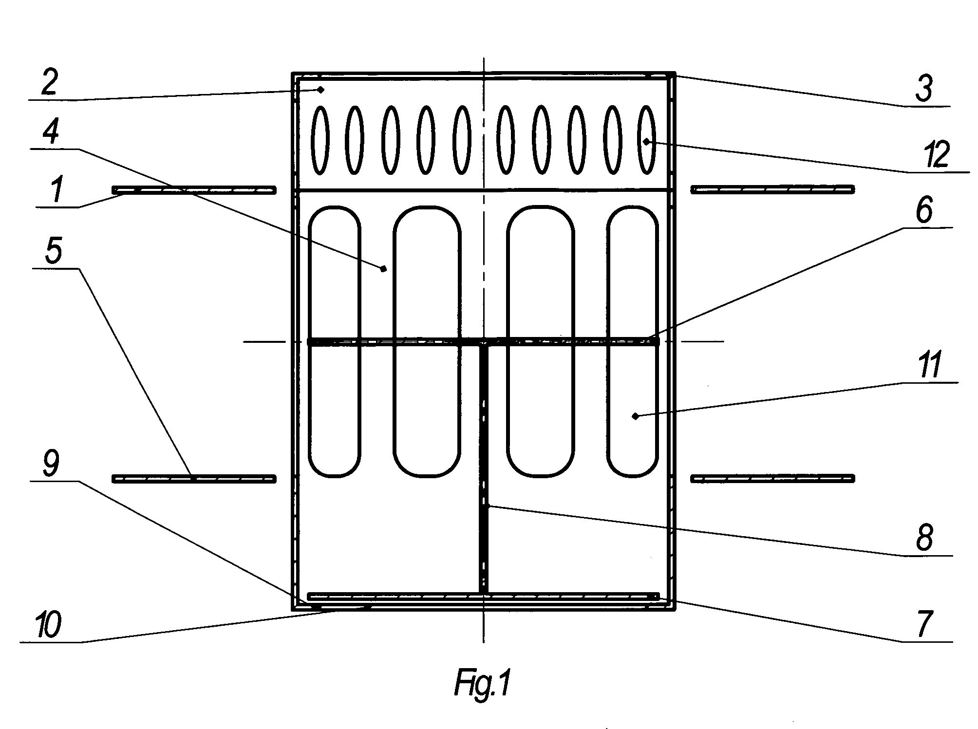
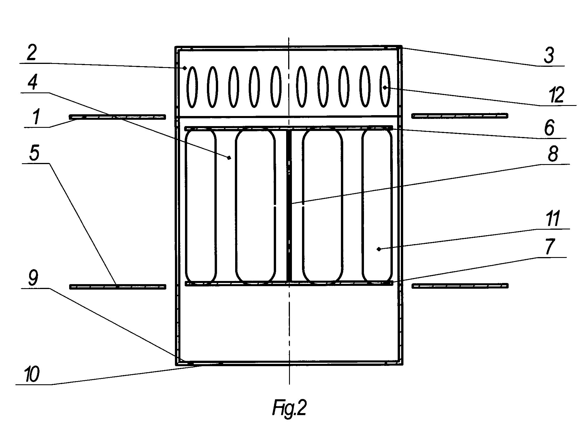
[0032]As illustrated on FIGS. 1,2,3, according to the parent embodiment (disclosed in the U.S. patent application Ser. No. 12 / 227,991), the inventive mass-exchange contact device comprises an essentially flat ring-shaped upper tray (1) attached with its outward edge to the walls of a conventional rectification column (not illustrated in FIGS. 1,2,3).

[0033]The inventive device comprises a cylindrical sleeve (4) attached to the inward edge of the upper tray 1, the sleeve 4 includes a top opening with a ring-shaped ascending limiter (3) surrounding the top opening, and a bottom opening (10) with a ring-shaped descending limiter (9) surrounding the bottom opening. The limiters 3 and 9 can be made as folded edges of the sleeve 4. The sleeve 4 includes a plurality of vertically extended windows (11) made in its sidewalls so that the top edges of the windows 11 are situated in the plane of upper tray 1. The sidewalls of sleeve 4 in their upper region are attached to the inward edge o...

second embodiment

Continuation

[0044]A common problem of the related art devices (as well as of the device of the first embodiment) can be described as follows: an ideal mass-exchange process for separate movements of the liquid and volatile phases envisages a 100% intermingling of the phases during the introduction of the volatile phase, whose concentration changes during the mass-exchange process. In case of the 100% intermingling, the change of concentration xn of the volatile phase occurs during a time t of passage of the volatile phase throughout an entire volume of the liquid phase according to a dependence of dxn / dt. However, if one could orderly alter the concentration of the volatile phase along a height (z) of the liquid phase component, it would lead to an increase of the efficiency of separation of the liquid and volatile components on the mass-exchange tray according to a dependency of d2xn / dtdz.

[0045]This problem is herein solved in the second embodiment of inventive device / method for im...

third embodiment

Continuation

[0056]The third embodiment of inventive device / method is provided for improvement of mass-exchange between a volatile phase and a liquid phase, wherein the mass-exchange takes place simultaneously with a catalytic distillation process within the same column. The third embodiment is illustrated on FIGS. 6 and 7. The third embodiment basically includes elements identical to the elements of the second embodiment. However, according to the third embodiment, the space between the layers of package fittings 15 is filled out with a suitable conventional catalytic material (16).

[0057]A column 20 (FIGS. 6 and 7) contains an upper row and a lower row of mass exchange contact devices, designed according to the first embodiment (taught in the U.S. patent application Ser. No. 12 / 227,991), wherein each of the rows is combined with a packing fitting 15 placed above thereof, and containing the catalytic material 16. FIG. 6 shows the state wherein the volatile phase is not introduced, wh...


PUM


Abstract

A mass-exchange contact device is proposed, comprising upper and lower flat ring-shaped trays attached to a column, a sleeve having windows with bottom edges in the plane of the lower tray, a barbotage unit having orifices in its sidewalls placed on the top sleeve, a movable double-acting valve including upper and lower plates connected with a rod. The barbotage unit includes an ascending limiter of valve's movement, the sleeve's bottom includes a descending limiter. Alternatively, the barbotage unit is made as a portion of the sleeve. Embodiments comprise a number of rows of the proposed devices situated one above the other, and separated by multi-layer packing fittings. The devices can be used in catalytic distillation columns, wherein the fittings are filled with catalytic material. Alternatively, the fitting is substituted with a grating supporting a catalytic granular layer. The proposed design improves device operation, reliability, durability, reduces its weight and costs.

Description

CROSS-REFERENCE TO RELATED APPLICATIONS[0001]This U.S. patent application is a continuation-in-part application of a U.S. patent application Ser. No. 12 / 227,991 (herein further referred to as “parent application”) filed on 4 Dec. 2008, entitled “Mass-Exchange Contact Device”, being a U.S. national phase application of a PCT application PCT / UA2007 / 000038 filed on 7 Jun. 2007, published as WO2007 / 145604, which PCT application claims priority of a Ukrainian patent application UA2006 / 06612 filed on 13 Jun. 2006. This continuation-in-part application also claims priority of another PCT application PCT / UA2010 / 000005 filed on 22 Feb. 2010, claiming priority of a Ukrainian patent application UA200901774 filed on 2 Mar. 2009. The foregoing PCT applications and Ukrainian applications are hereby entirely incorporated by reference. The U.S. patent application Ser. No. 12 / 227,991 (parent application) is hereby expressly abandoned.FIELD OF THE INVENTION[0002]The invention relates to mass exchange...

Claims


Application Information

Patent Timeline
Patent Type & Authority Patents(United States)
IPC IPC(8): B01J8/04B01D3/18
CPCB01D3/163Y02P20/10
Inventor MALETA, BOGDANMALETA, OLESIA
Owner MALETA BOGDAN
Learn More