Variable displacement compressor

a compressor and variable displacement technology, applied in the direction of machines/engines, multi-cylinder pumps, positive displacement liquid engines, etc., can solve the problems of destroying the reliability of the compressor, and achieve the effect of simplifying the processing of cylinder blocks

Inactive Publication Date: 2010-12-28
SANDEN CORP
View PDF46 Cites 2 Cited by
  • Summary
  • Abstract
  • Description
  • Claims
  • Application Information

AI Technical Summary

Benefits of technology

[0012]Accordingly, an object of the present invention is to provide a structure of a variable displacement compressor which enables a high-reliability displacement changing control with no foreign matter accumulation in a passageway provided for displacement control, and which makes it possible to simplify particularly the processing of a cylinder block.
[0015]In such a variable displacement compressor according to the present invention, only when a valve body of the displacement control valve is operated in its opening direction, for a moment a flow from the discharge chamber side to the crank chamber side occurs transiently, and usually a flow from the crank chamber side to the suction chamber side occurs. In the present invention, because a part of the discharge pressure supply passageway capable of communicating from the discharge chamber side to the crank chamber side and a part of the pressure relief passageway communicating from the crank chamber side to the suction chamber side are formed as a common passageway communicating with an end of the crank chamber, at this portion of the common passageway, a bidirectional flow occurs accompanying with the operation for the displacement control. Since this common passageway is formed by a gap between the compressor main shaft and the bearing, the gas chamber containing a bearing supporting member which is formed at a shaft end extended portion of the compressor main shaft, etc., the bidirectional flow occurs in these portions. By generating the bidirectional flow, even in a low flow speed range, foreign matters in the gas are not likely to be accumulated on the way of these passageway portions, thereby greatly increasing the reliability and durability of the compressor.
[0016]Further, because the discharge pressure supply passageway portion communicating with an end of the crank chamber and the pressure relief passageway portion are formed as a common passageway, a portion to be processed as a passageway in the cylinder block decreases, and the processing may be simplified. By simplifying the processing, facilitation of the processing and cost down may be expected.
[0017]Moreover, if the fixed orifice is formed in the displacement control valve, because it is not necessary to form a passageway reaching the fixed orifice in the cylinder block, it becomes possible to further simplify the processing of the cylinder block and to further reduce the cost.

Problems solved by technology

Such a foreign matter accumulation may cause an abrasion of, in particular, bearing 77 or compressor main shaft 56, and may damage the reliability of the compressor.

Method used


Image

  • Variable displacement compressor
  • Variable displacement compressor
  • Variable displacement compressor

Examples


Embodiment Construction

[0022]Hereinafter, desirable embodiments of the present invention will be explained referring to figures.

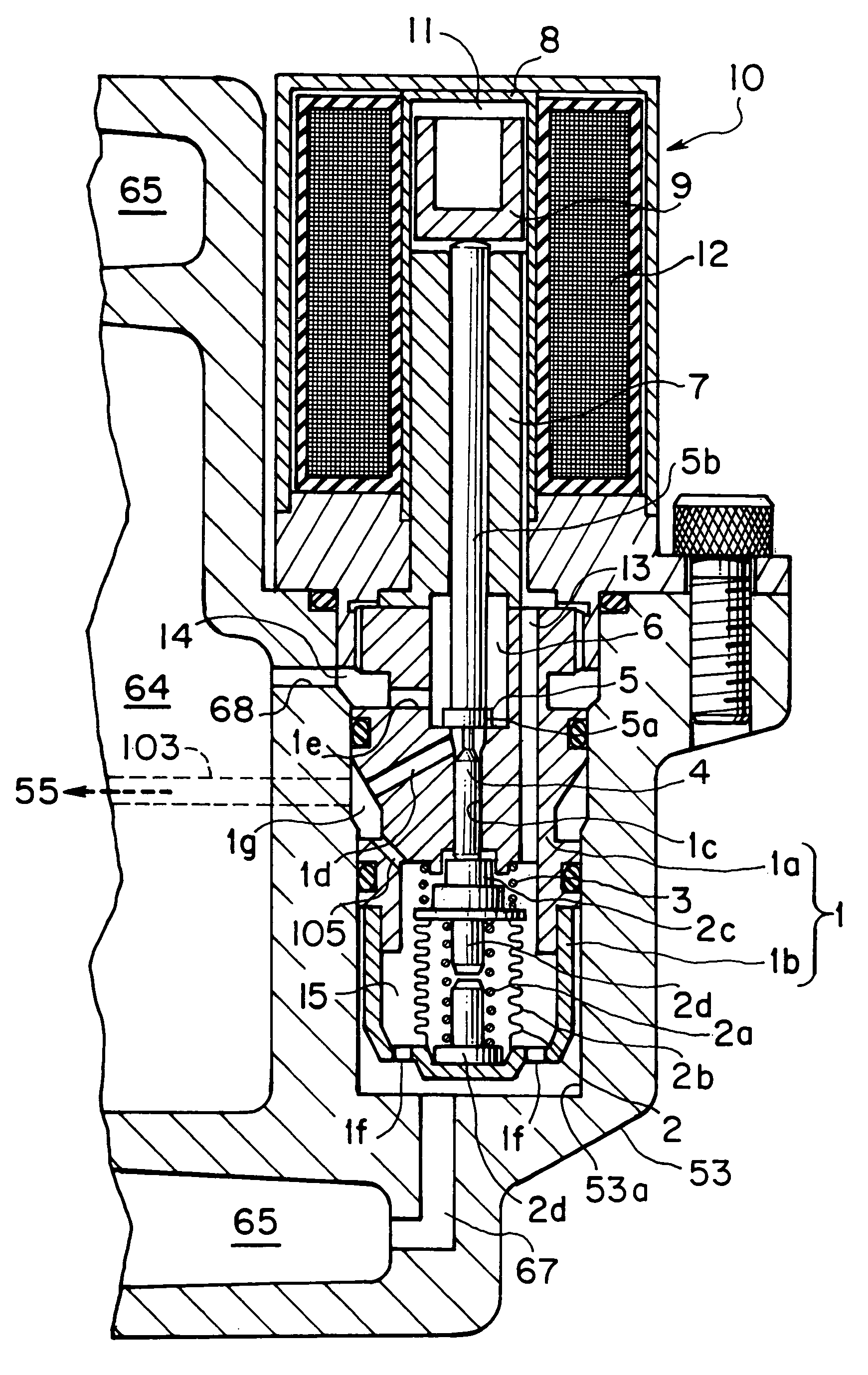
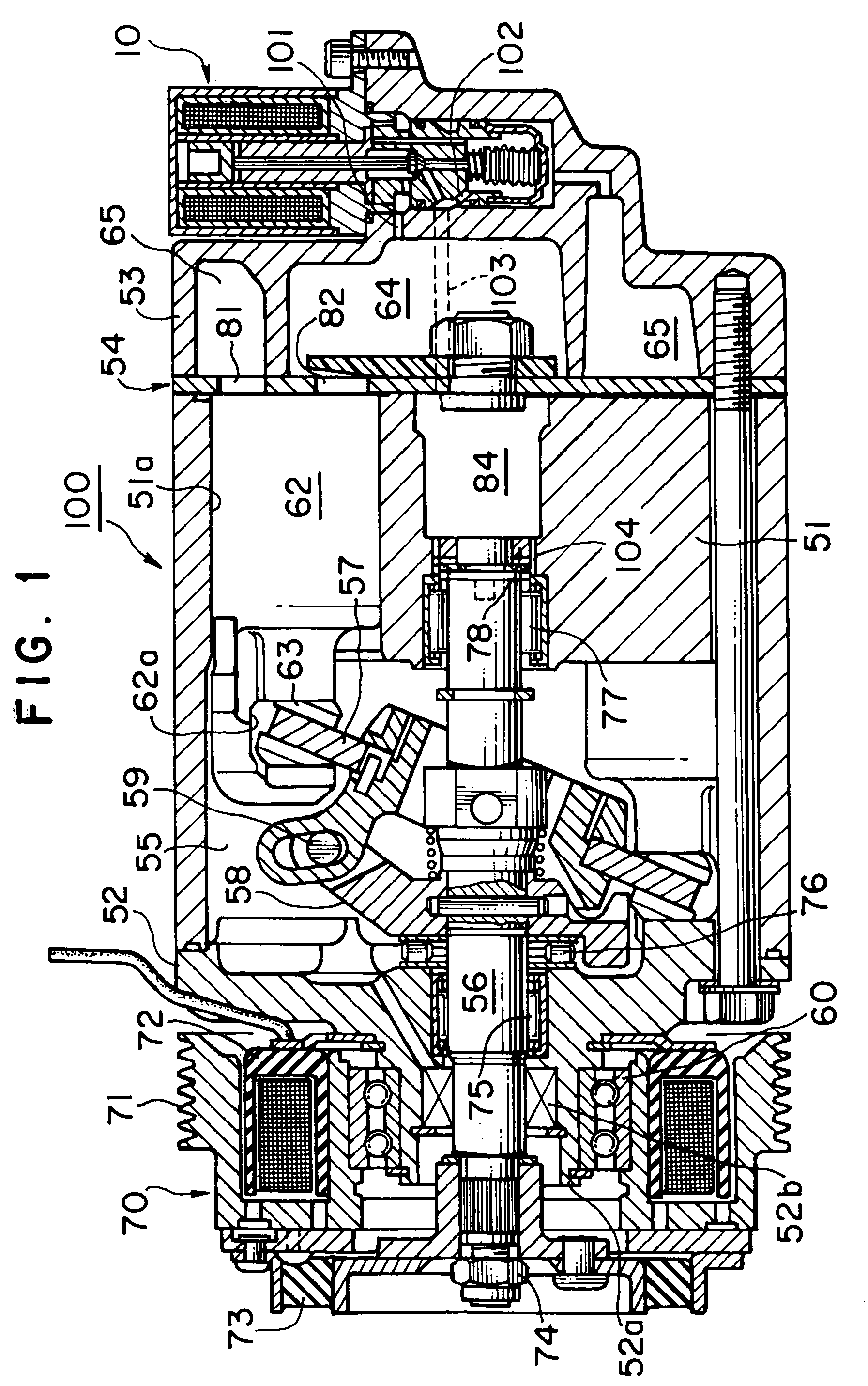
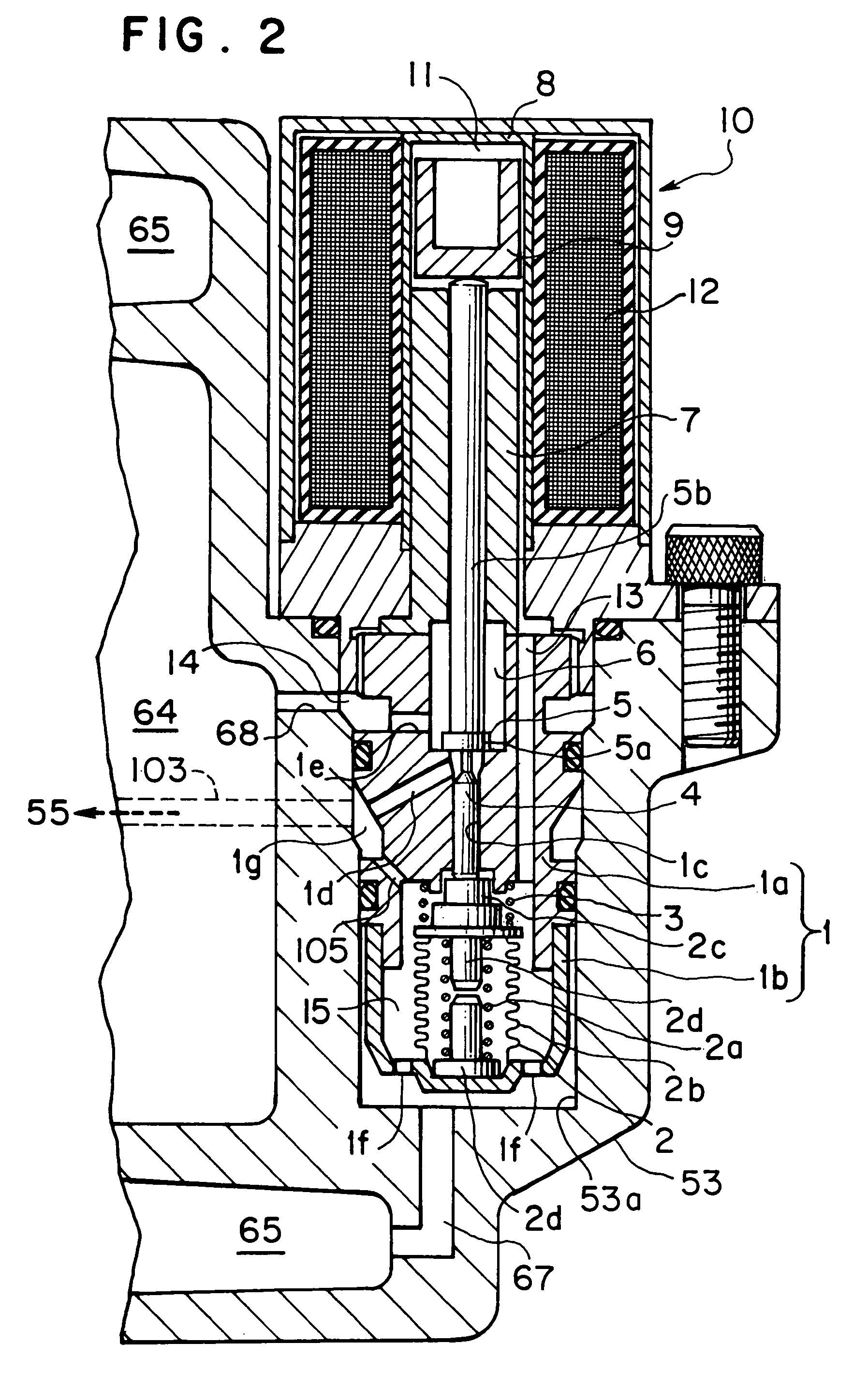
[0023]In the present invention, because the basic structures of portions other than a discharge pressure supply passageway and a pressure relief passageway of a variable displacement compressor are substantially the same as those depicted in FIGS. 3 and 4, here, mainly the discharge pressure supply passageway and the pressure relief passageway will be explained. FIGS. 1 and 2 depict a variable displacement compressor according to an embodiment of the present invention. In this embodiment, structures of discharge pressure supply passageway 101 and pressure relief passageway 102 are different from those shown in FIGS. 3 and 4, and because the structures of the other portions are substantially the same as those depicted in FIGS. 3 and 4, the explanation thereof will be omitted by giving the same symbols as those of FIGS. 3 and 4 to the substantially same portions.

[0024]In a variable...


PUM


Abstract

A variable displacement compressor comprising a displacement control valve disposed somewhere in a discharge pressure supply passageway capable of communicating with a crank chamber from a discharge chamber, and a fixed orifice disposed somewhere in a pressure relief passageway communicating with a suction chamber from the crank chamber, the displacement control valve being controlled in opening / closing operation to adjust a pressure in the crank chamber to control a piston stroke, wherein a part of the discharge pressure supply passageway and a part of the pressure relief passageway are formed as a common passageway communicating with a crank chamber end. Variable displacement control at a high reliability is possible with no foreign matter accumulation in the displacement control passageway, and the processing of a cylinder block is simplified.

Description

TECHNICAL FIELD OF THE INVENTION[0001]The present invention relates to a variable displacement compressor used in an air conditioning system for vehicles, etc., and specifically to a variable displacement compressor capable of performing a variable displacement control at a high reliability with no foreign matter accumulation in a passageway provided for the displacement control and capable of simplifying the processing of the compressor.BACKGROUND ART OF THE INVENTION[0002]As a variable displacement compressor provided in a refrigeration circuit of an air conditioning system for vehicles, etc., a compressor such as one disclosed in JP-A-2000-18172 is known. As depicted in FIG. 3, this variable displacement compressor 50 has a cylinder block 51 with a plurality of cylinder bores 51a, a front housing 52 provided at one end of cylinder block 51, and a rear housing 53 provided to cylinder block 51 via a valve plate device 54. A compressor main shaft 56 is provided as a drive shaft acro...

Claims


Application Information

Patent Timeline
Patent Type & Authority Patents(United States)
IPC IPC(8): F04B1/26F04B27/18F04B27/10
CPCF04B27/1804F04B2027/1813F04B2027/1827F04B2027/1854F04B2027/1859F04B2027/1895
Inventor TAGUCHI, YUKIHIKO
Owner SANDEN CORP
Why Eureka
Try Eureka