
Head suspension piezoelectric actuator with a nonconductive adhesive joining together the circumferential edge of an actuator base opening with a circumferential side face of the piezoelectric element

a piezoelectric actuator and nonconductive adhesive technology, applied in the direction of maintaining the alignment of the head carrier, recording information storage, instruments, etc., can solve the problem of not taking corrective measures

Active Publication Date: 2012-12-18
NHK SPRING CO LTD
View PDF14 Cites 1 Cited by
  • Summary
  • Abstract
  • Description
  • Claims
  • Application Information

AI Technical Summary

Benefits of technology

The present invention provides a head suspension that securely holds and fills the gap between the actuator base and the piezoelectric element, while also securing electric insulation between the electrode of the piezoelectric element and the actuator base. This is achieved by using a nonconductive adhesive part and a nonconductive filler in a circumferential channel between the actuator base and the piezoelectric element. The technical effect of this invention is to improve the performance and reliability of the head suspension.

Problems solved by technology

An important issue for the head suspension employing the dual actuator system is to protect the brittle piezoelectric elements from damage and secure electric insulation between the head suspension body and the piezoelectric elements.
According to the related art, this gap must be relatively large to cover dimensional allowances of each opening and piezoelectric element, an operational error of an automatic assembling machine used to attach the piezoelectric elements to the openings, and the like.
The related art, however, takes no measures to correctly keep the gap between the circumferential edge of the opening and the circumferential side face of the piezoelectric element, properly fill the gap with a nonconductive material, and secure electric insulation between an electrode of the piezoelectric element and the actuator base.

Method used


Image

  • Head suspension piezoelectric actuator with a nonconductive adhesive joining together the circumferential edge of an actuator base opening with a circumferential side face of the piezoelectric element
  • Head suspension piezoelectric actuator with a nonconductive adhesive joining together the circumferential edge of an actuator base opening with a circumferential side face of the piezoelectric element
  • Head suspension piezoelectric actuator with a nonconductive adhesive joining together the circumferential edge of an actuator base opening with a circumferential side face of the piezoelectric element

Examples


first embodiment

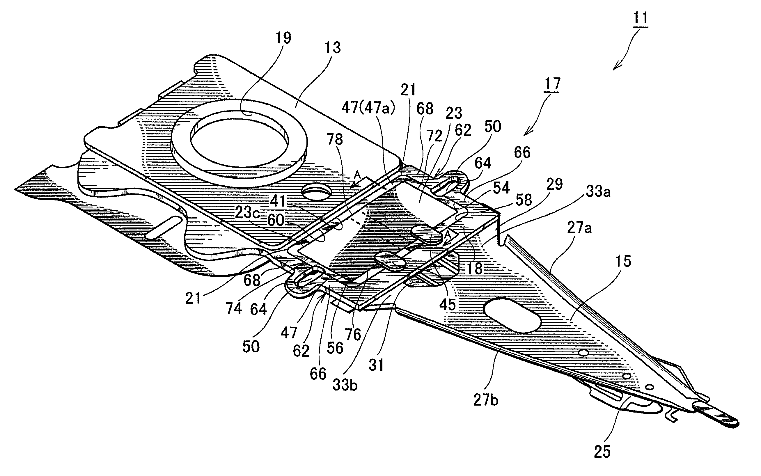
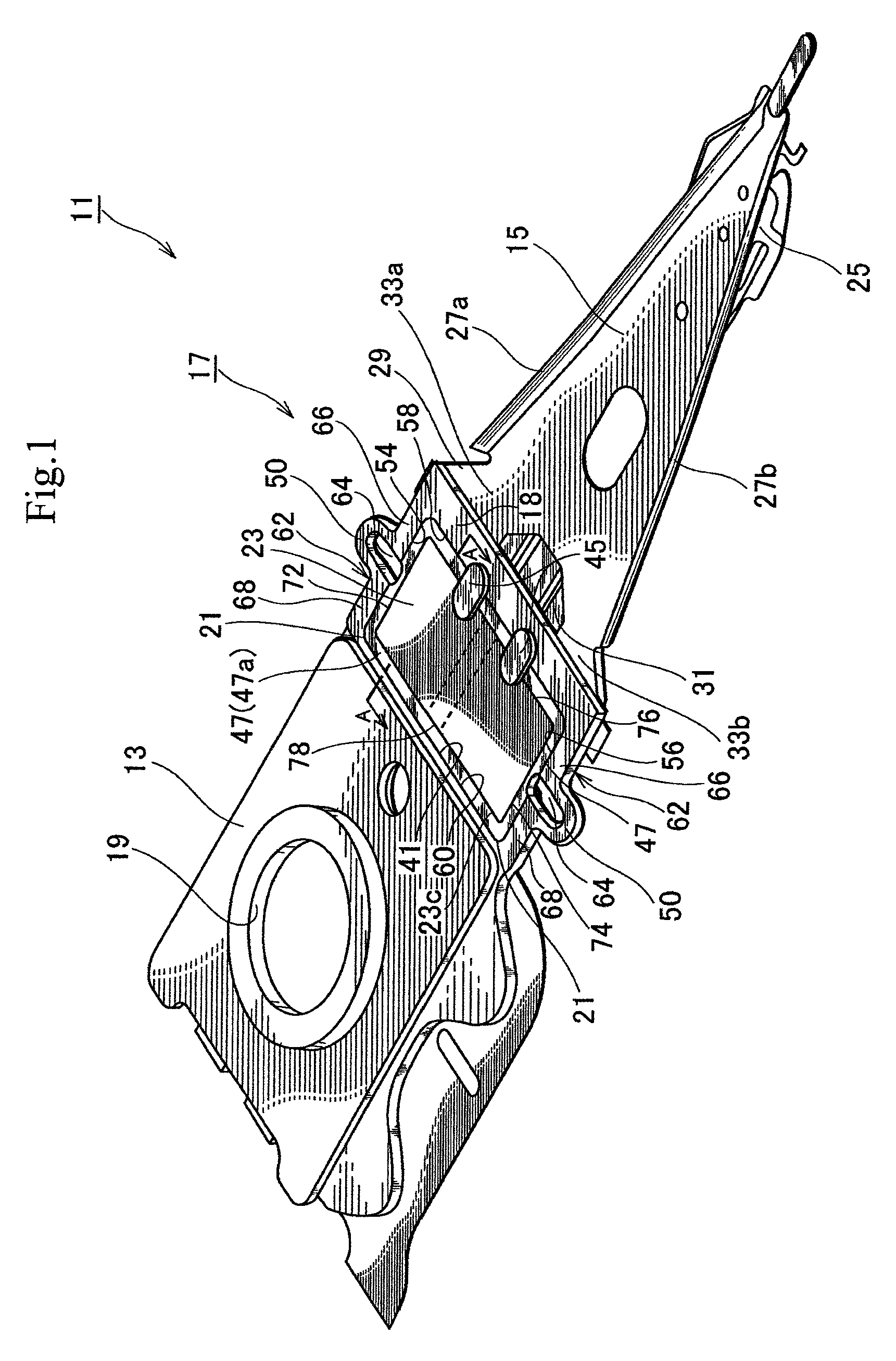
[0027]FIG. 1 is a perspective view illustrating a head suspension 11 according to the present invention. In FIG. 1, the head suspension 11 has a base plate 13, a load beam 15, and a piezoelectric actuator 17.

[0028]The base plate 13 is a metal thin plate made of, for example, stainless steel and has a thickness of about 150 to 200 μm. The base plate 13 may be made of light metal such as aluminum alloy or a clad material having of light metal and stainless steel. The light metal can reduce the inertia of the base plate 13, increase the resonant frequency of the head suspension 11 in a sway direction, i.e., a widthwise direction of the head suspension 11, and improve the tracing performance of the head suspension 11.

[0029]The base plate 13 has a circular boss 19. With the boss 19, the base plate 13 is attached to a front end of an actuator arm (not illustrated) and is turned by a voice coil motor (not illustrated). The base plate 13 has a front end in the vicinity of the load beam 15 a...

embodiment 1

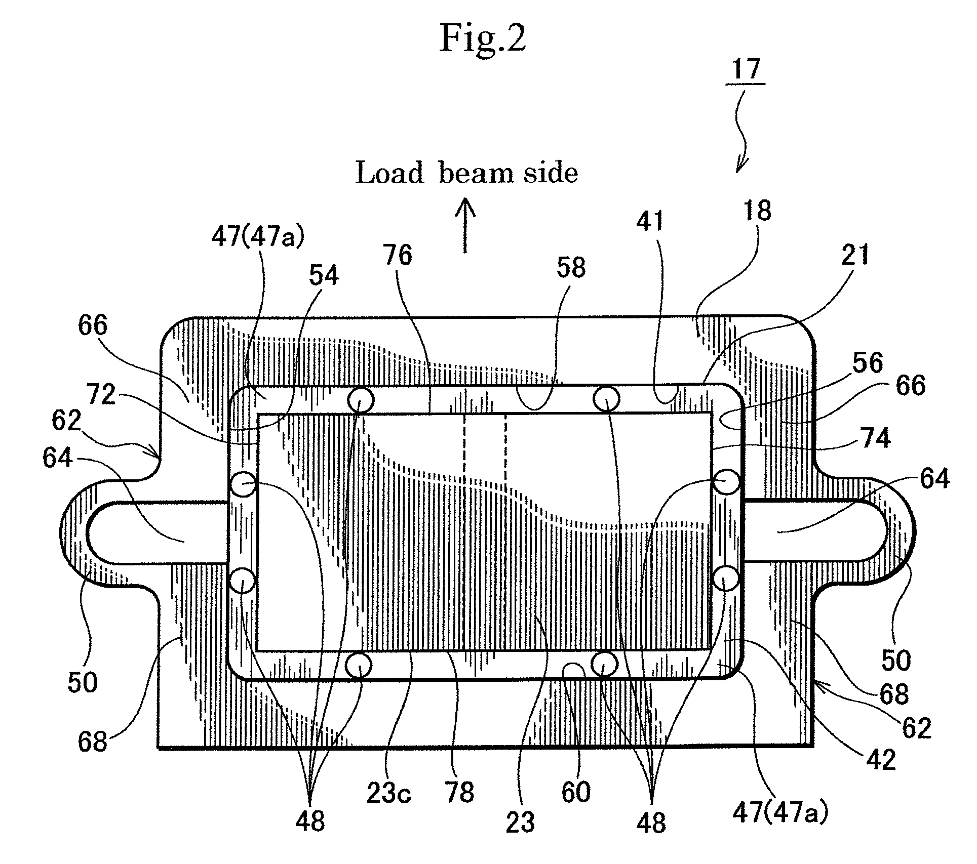
[0033]The piezoelectric actuator 17 that is an essential part of the head suspension 11 will be explained also with reference to FIGS. 2 and 3 in which FIG. 2 is an enlarged plan view illustrating the piezoelectric actuator 17 and FIG. 3 is a sectional view taken along a line A-A of FIG. 1.

[0034]When designing the piezoelectric actuator 17, considerations must be made to effectively transfer a distortion (displacement) of the piezoelectric element 23 to the load beam 15, secure electric insulation between an electrode of the piezoelectric element 23 and an actuator base 18, prevent dust from dropping off a circumferential side surface 23c of the piezoelectric element 23, and protect the brittle piezoelectric element 23 from being damaged.

[0035]In consideration of these points, the piezoelectric actuator 17 of the first embodiment is accomplished.

[0036]As shown in FIGS. 1 and 2, the piezoelectric actuator 17 functions to support a base part of the load beam 15 and move a front end o...

second embodiment

[0102]A head suspension according to the present invention will be explained with reference to FIG. 7.

[0103]The head suspension 61 according to the second embodiment is configured basically the same as the head suspension 11 of the first embodiment. In this embodiment, like parts are represented with like reference marks of the first embodiment and differences between the first and second embodiments will mainly be explained.

[0104]According to the first embodiment, the piezoelectric actuator 17 of the head suspension 11 has the flexible links 50 on outer sides of the opening 21 of the actuator base 18, each of the flexible links 50 having a U-shape protruding outwardly from the opening 21.

[0105]According to the second embodiment, the head suspension 61 has a piezoelectric actuator 63 having an actuator base 18 in which an opening 21 is formed. On each outer side of the opening 21, a clearance 52 instead of the flexible link 50 of the first embodiment is formed.

[0106]Each clearance 5...


PUM

PropertyMeasurementUnit
thicknessaaaaaaaaaa
thicknessaaaaaaaaaa
thicknessaaaaaaaaaa

Abstract

The piezoelectric actuator of a head suspension has an actuator base and at least a piezoelectric element, the actuator base connected to the base part of the load beam of the suspension and having at least an opening, the piezoelectric element attached to the opening and deforming in response to a voltage applied thereto to effect displacement of the front end of the load beam. A nonconductive filler is fitted into a circumferential channel defined between a circumferential edge of an opening in the actuator base and a circumferential side face of the piezoelectric element facing the circumferential edge of the opening to maintain a width of the circumferential channel. A nonconductive adhesive part is formed in the circumferential channel and joins the circumferential edge of the opening and the circumferential side face of the piezoelectric element together.

Description

BACKGROUND OF THE INVENTION[0001]1. Field of the Invention[0002]The present invention relates to a head suspension for a disk drive incorporated in an information processing apparatus such as a personal computer, and particularly, to a head suspension having a piezoelectric element that is attached with a nonconductive adhesive and deforms in response to a voltage applied thereto.[0003]2. Description of Related Art[0004]Small-sized, precision information devices are rapidly advancing, and for use with such devices, needs for micro-actuators capable of conducting positioning control for very small distances are increasing. Such micro-actuators are highly needed by, for example, optical systems for correcting focuses and inclination angles, ink jet printers for controlling ink heads, and magnetic disk drives for controlling magnetic heads.[0005]The magnetic disk drives are strongly expected to increase their storage capacities. Increasing the storage capacity of a magnetic disk drive ...

Claims


Application Information

Patent Timeline
Patent Type & Authority Patents(United States)
IPC IPC(8): G11B5/58G11B21/24
CPCG11B5/4833G11B5/4873
Inventor KASHIMA, HIDEKI
Owner NHK SPRING CO LTD
Learn More