
Procedure for deriving a three-dimensional digital mask starting from a series of two-dimensional masks, plus a device for doing this

a three-dimensional digital mask and two-dimensional mask technology, applied in the field of radiographic devices and methods, can solve the problems of reducing the number of false positives, constructing reliable three-dimensional masks, and reducing the number of false negatives

Active Publication Date: 2012-12-18
GENERAL ELECTRIC CO
View PDF5 Cites 0 Cited by
  • Summary
  • Abstract
  • Description
  • Claims
  • Application Information

AI Technical Summary

Benefits of technology

This method provides regular and consistent two-dimensional masks and accurate three-dimensional reconstructions without underestimating object shape, reducing artefacts and improving diagnostic quality by eliminating discontinuities.

Problems solved by technology

The principle difficulties in constructing reliable three-dimensional masks derive from the limited angular interval swept out by the source and the truncation of the object under consideration in some projections as a result of the finite dimensions of the detector.
Multiple views projected from different angles of acquisition potentially reduce the number of false positives due to the addition of artefacts, and the number of false negatives due to masking effects by the covering tissues.
The contour of the resulting mask is therefore a poor estimation of what it really should be, and the shape of the mask is not continuous.
In consequence, using the three-dimensional mask obtained this way on the three-dimensional representation produces an unnatural skin line in the final three-dimensional representation, which complicates the diagnoses that the practitioners make based on it.

Method used


Image

  • Procedure for deriving a three-dimensional digital mask starting from a series of two-dimensional masks, plus a device for doing this
  • Procedure for deriving a three-dimensional digital mask starting from a series of two-dimensional masks, plus a device for doing this
  • Procedure for deriving a three-dimensional digital mask starting from a series of two-dimensional masks, plus a device for doing this

Examples


Embodiment Construction

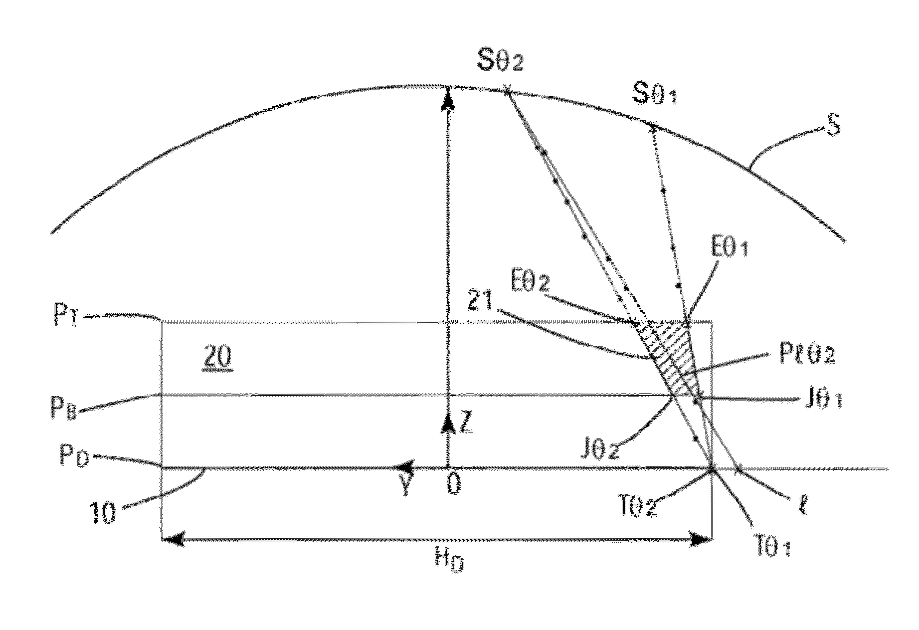
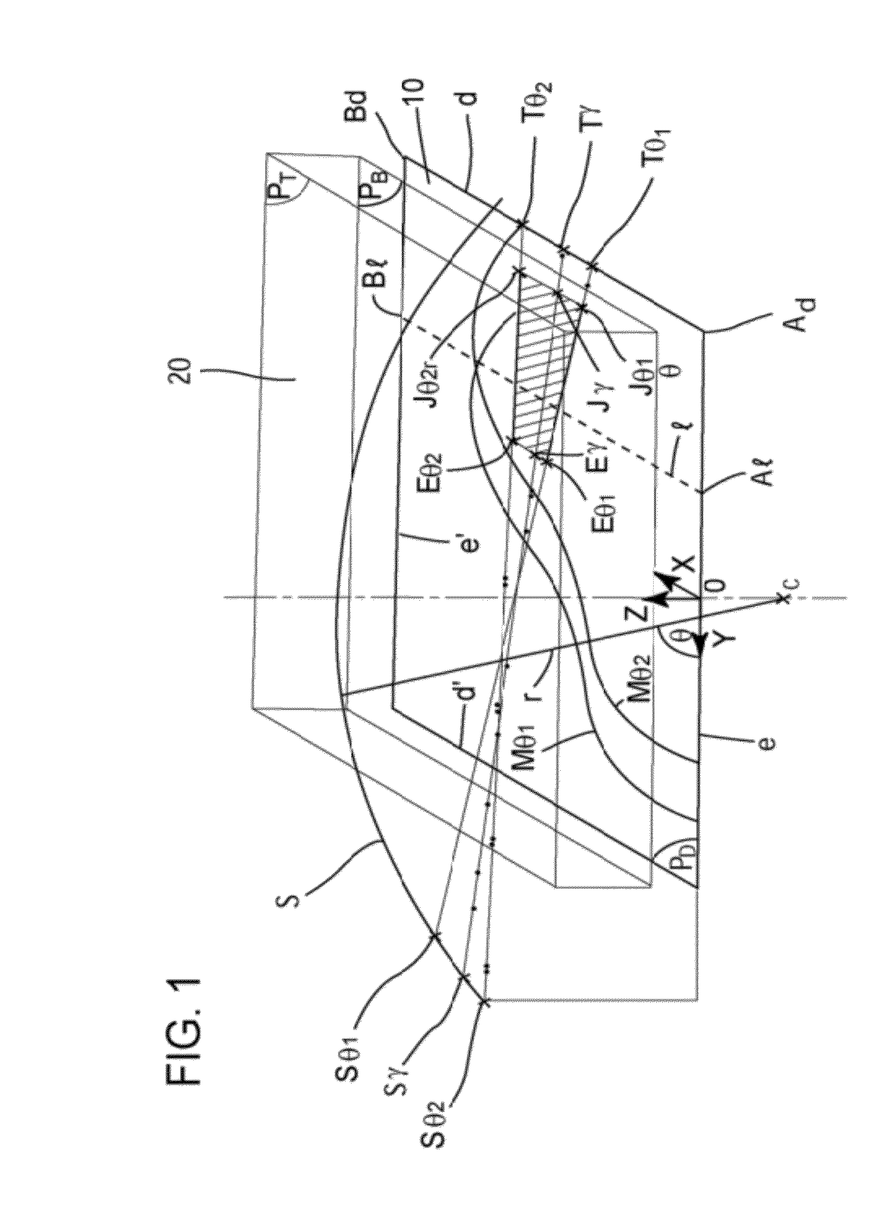
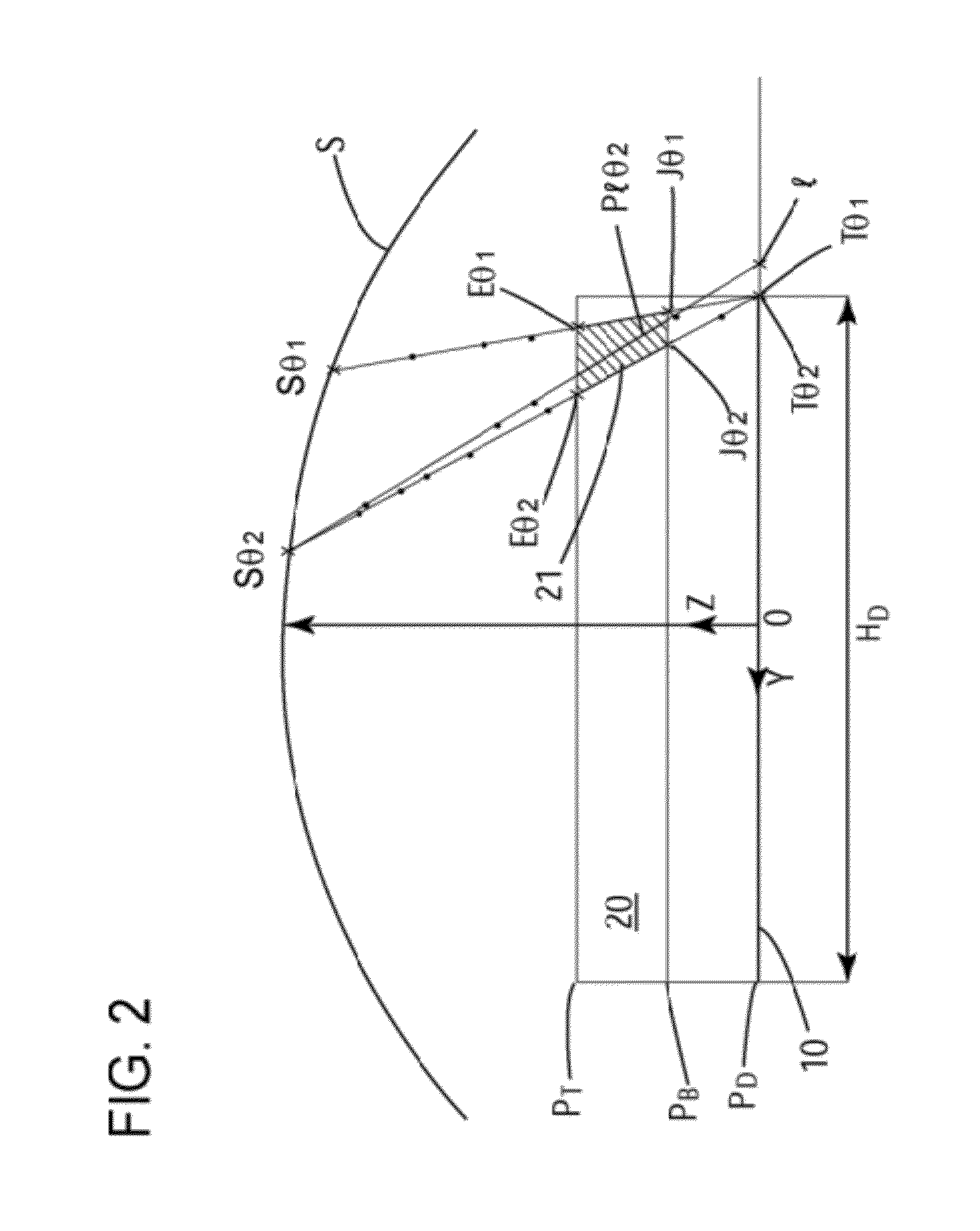
[0053]With reference to FIG. 1: a radiographic device suitable for producing imagery by three-dimensional tomography contains a means of recording 10 that takes the form of a digital detector that is effectively flat and defines a plane PD. A digital detector such as this comprises a matrix of detectors each of which represents a pixel p, uniformly distributed into lines and columns. The radiographic device also includes an X-ray source opposite the means of recording and which is mobile with respect to this same means of recording. The X-ray source, which will generally be an X-ray generator tube, is suitable for being moved in discrete steps along a trajectory S that is effectively a circle of radius r and centre C. The trajectory S is restricted in terms of angle to an interval of range [θmin; θmax], where 0≦θminmax≦π, and where the angles are measure with respect to the plane PD of the detector. At each discrete source position Sθ along this trajectory S, there are an associated...


PUM


Abstract

A derivation procedure for a three-dimensional digital mask from a series of two-dimensional masks in a radiographic device containing a source (S) of X-rays, a means of recording and a volume of interest hat contains the object to be X-rayed located between the source (S) and the means of recording consists of an extrapolation of each mask Mθ2 includes determining a last segment 1fin beyond the limits of the means of recording; and working out a two-dimensional mask Mγ associated with a position Sγ of the source, for any angle γ included in the angular range θ2 to θ1 (a position close to θ2). For every parallel segment 1 located between segment d (or d′ respectively) and segment 1fin, the procedure further includes deriving a three-dimensional mask (21) of the object for each voxel at the intersection of plane P1θ2 and the volume of interest; and projecting the three-dimensional mask onto the segment 1.

Description

CROSS-REFERENCE TO RELATED APPLICATIONS[0001]This application claims priority under 35 U.S.C. §119(a)-(d) or (f) to prior-filed, co-pending French patent application serial number 0760151, filed on Dec. 20, 2007, which is hereby incorporated by reference in its entirety.STATEMENT REGARDING FEDERALLY SPONSORED RESEARCH OR DEVELOPMENT[0002]Not ApplicableNAMES OF PARTIES TO A JOINT RESEARCH AGREEMENT[0003]Not ApplicableREFERENCE TO A SEQUENCE LISTING, A TABLE, OR COMPUTER PROGRAM LISTING APPENDIX SUBMITTED ON COMPACT DISC[0004]Not ApplicableBACKGROUND OF THE INVENTION[0005]1. Field of the Invention[0006]The field of the invention relates to radiographic devices and methods generally. More particularly, the field of the invention is concerned with an extrapolation procedure for a two-dimensional mask and a procedure for working out a three-dimensional mask based on an extrapolated series of two-dimensional masks, these procedures being intended for use in a radiographic device, particul...

Claims


Application Information

Patent Timeline
Patent Type & Authority Patents(United States)
IPC IPC(8): G06F17/17G06K9/00
CPCG06T11/005G06T2207/10112G06T2207/30068A61B6/027
Inventor PALMA, GIOVANNIMULLER, SERGEIORDACHE, RAZVAN
Owner GENERAL ELECTRIC CO
Learn More