Rainscreen attachment system

a technology of attachment system and acm, which is applied in the field of attachment system of acm aluminum panel, can solve the problems of high labor intensity of current acm aluminum panel attachment method, large amount of aluminum extrusion, and high cost of overall system compared to other buildings, and achieve the effect of reducing labor and material requirements and easy attachmen

Active Publication Date: 2012-12-25
BOARD OF REGENTS FOR OKLAHOMA STATE UNIVERSITY
View PDF47 Cites 29 Cited by
  • Summary
  • Abstract
  • Description
  • Claims
  • Application Information

AI Technical Summary

Benefits of technology

[0006]The invention is a method and apparatus for attaching panels, e.g., aluminum composite material (ACM) panels, to the exterior of buildings to create a drained / back-ventilated rainscreen. The system is based on the Drained / Back Ventilated (D / B-V) Rainscreen principle. The system will allow air to flow freely behind the panels, thereby providing a means of removing moisture from the interior of the panels. The system will allow some water penetration, but will control this water using a guttering network. The system consists of a series of interlocking brackets and panel configurations that allow the panels to be attached easily, allow airflow behind the panels, allow for the thermal expansion and contraction of the panels, allow for guttering of water, and reduce the labor and material requirements when compared to existing systems.
[0007]By creating a novel panel configuration that allows the panels to overlap, the Improved Rainscreen Attachment System (IRAS) eliminates the need to fill the gap between panels with additional components. In the system of the invention, the reveal strip is integrated into the right side of a left panel. The reveal strip is formed from the ACM and therefore requires no additional painting or means of fastening. Standard hat furring channel, a very common building material, is located behind the joint gap and serves as an inexpensive means of guttering in the vertical direction any water that penetrates the vertical joint as well as water that has been channeled there by the horizontal joint guttering system.
[0008]In the improved rainscreen attachment system of the invention, guttering in the horizontal direction is achieved by a channel that is formed out of panel material and is an integral part of the panel. Again, because the channel is integrated into the panel, the channel requires no additional painting or means of fastening. The horizontal joint prevents rainwater from getting behind the panels yet allows for air to flow freely in behind the panels. This air flow provides a means of removing moisture from the inside of the panels.
[0010]Upper brackets provide a rigid framework for the gutter section of the ACM. The upper brackets also serve as the means of attaching the panel to the wall and create a gap, e.g., 1 inch, between the panel and the wall to allow for adequate airflow between the wall and the panel.

Problems solved by technology

Current aluminum composite material (ACM) panel attachment methods are labor intensive and require a large amount of aluminum extrusions.
This makes the overall system costly when compared to other building siding materials.
A water-tight system is difficult to achieve in practice and does not allow for the removal of moisture trapped in the interior of the panels.

Method used


Image

  • Rainscreen attachment system
  • Rainscreen attachment system
  • Rainscreen attachment system

Examples


Embodiment Construction

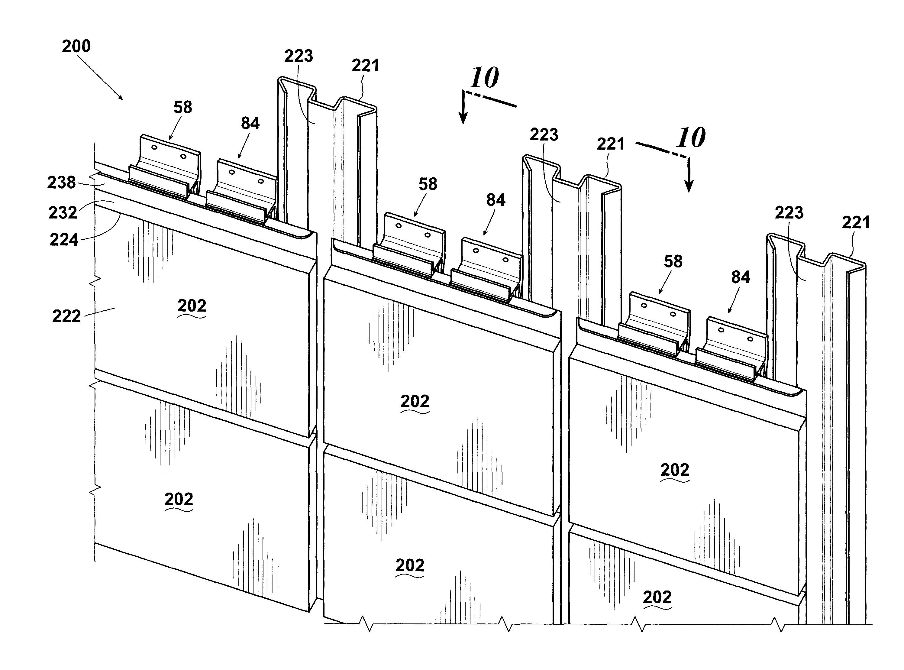
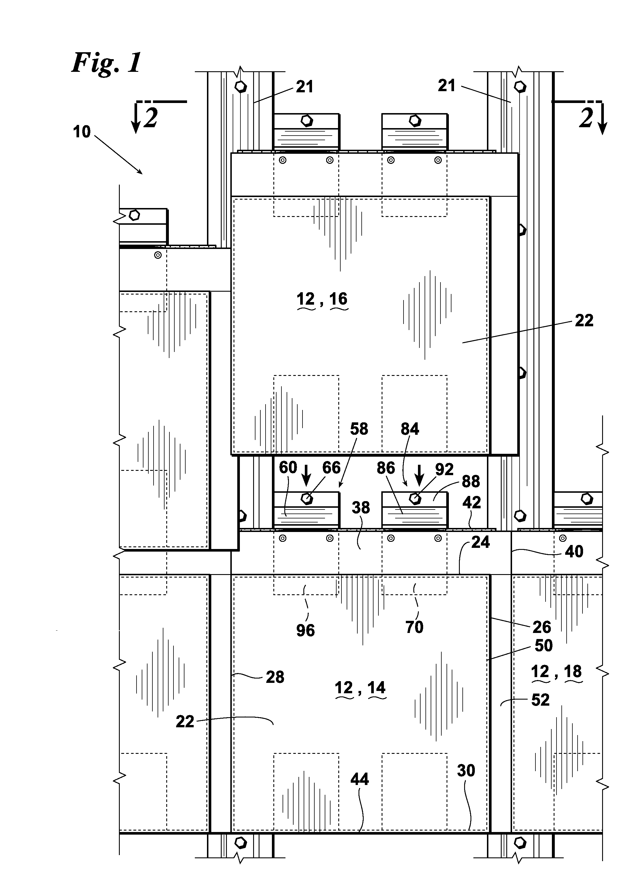
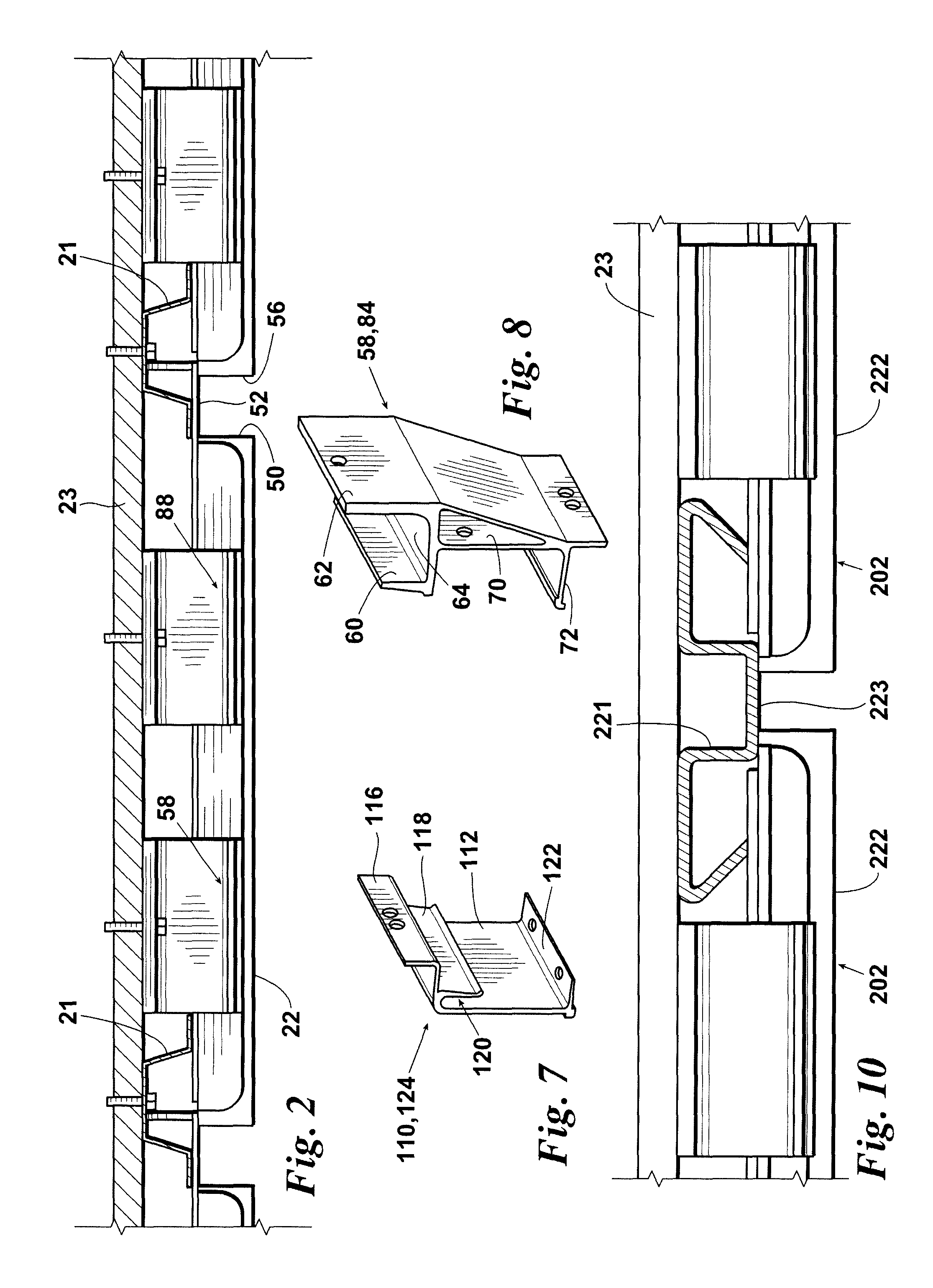
[0023]A wall mounted panel system designated generally 10 comprises a plurality of panels 12. A plurality of panels 12, for example first panel 14, second panel 16, third panel 18, fourth panel 20. Hat channels 21 are affixed to a wall surface 23 behind panels 12. Hat channels 21 are located behind a joint gap formed by adjacent panels and functions as a vertical gutter for any water that may migrate behind the panels. First panel 14 includes a main vertical member 22 having a top edge 24, right edge 26, left edge 28, and bottom edge 30. Panels 12 are preferably constructed of a composite aluminum skin bonded to a polyethylene core. The aluminum skin material may be machined from one side to facilitate bending of the material, e.g., to create edges 24, 26, 28, and 30.

[0024]Top member 32 (FIGS. 4, 5) has an inside surface and an outside surface. Top member 32 and main vertical member 22 have an inside surface that defines a recess 36 (FIGS. 4-6) where members 22 and 32 join, i.e., wh...


PUM


Abstract

A wall mounted panel system wherein panels are permitted three directions of expansion and contraction since each of panel is affixed to the wall at a single point. For example, the system includes a first and second panel adjacent to one another. An upper bracket and a lower bracket are affixed to the back of each panel, wherein the upper brackets are affixed to the wall and wherein the lower bracket of the first panel is movably engaged with the upper bracket of the second panel. The panels do not communicate with any sealing members, thereby allowing for air to flow freely behind the panels for providing a means of removing moisture from behind the panels. A brace member in communication with the interior surface of each panel has an upper end affixed to the upper bracket and a lower end affixed to the lower bracket.

Description

CROSS REFERENCE TO RELATED APPLICATIONS[0001]This application claims the priority of U.S. Provisional Patent Application No. 61 / 167,457 entitled “RAINSCREEN ATTACHMENT SYSTEM,” filed Apr. 7, 2009, the contents of which are hereby incorporated by reference.STATEMENT REGARDING FEDERALLY SPONSORED RESEARCH OR DEVELOPMENT[0002]This invention was made with government support under grant number SBAHQ-05-I-0061 awarded by the U.S. Small Business Administration. The government has certain rights in the invention.FIELD OF THE INVENTION[0003]A novel method of attaching building façade panels to the exterior of buildings to create a drained / back-ventilated rainscreen. More particularly, the invention consists of a series of brackets and panel configurations that allow the panels to be attached easily, allow airflow behind the panels, allow for the thermal expansion and contraction of the panels, allow for guttering of water, and reduce the labor and material requirements when compared to exist...

Claims


Application Information

Patent Timeline
Patent Type & Authority Patents(United States)
IPC IPC(8): E04B2/00
CPCE04F13/081E04F13/0842E04F13/12
Inventor ENNS, DOUGLAS BRENT
Owner BOARD OF REGENTS FOR OKLAHOMA STATE UNIVERSITY
Why Eureka
Try Eureka