
Layering non-metallic layers between metallic layers to improve armor protection

a non-metallic layer and armor protection technology, applied in armor, armor, weapons, etc., can solve the problems of increasing so as to reduce the length of the metallic channel formed by the projectile at each metallic layer, reduce the cost of armor solutions, and slow down the effect of projectile particles

Active Publication Date: 2012-12-25
RAYTHEON CO
View PDF14 Cites 6 Cited by
  • Summary
  • Abstract
  • Description
  • Claims
  • Application Information

AI Technical Summary

Benefits of technology

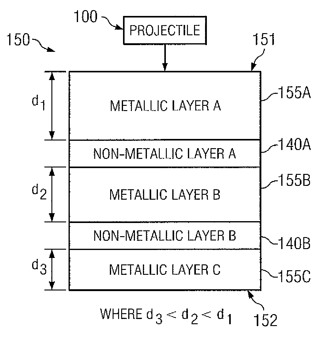
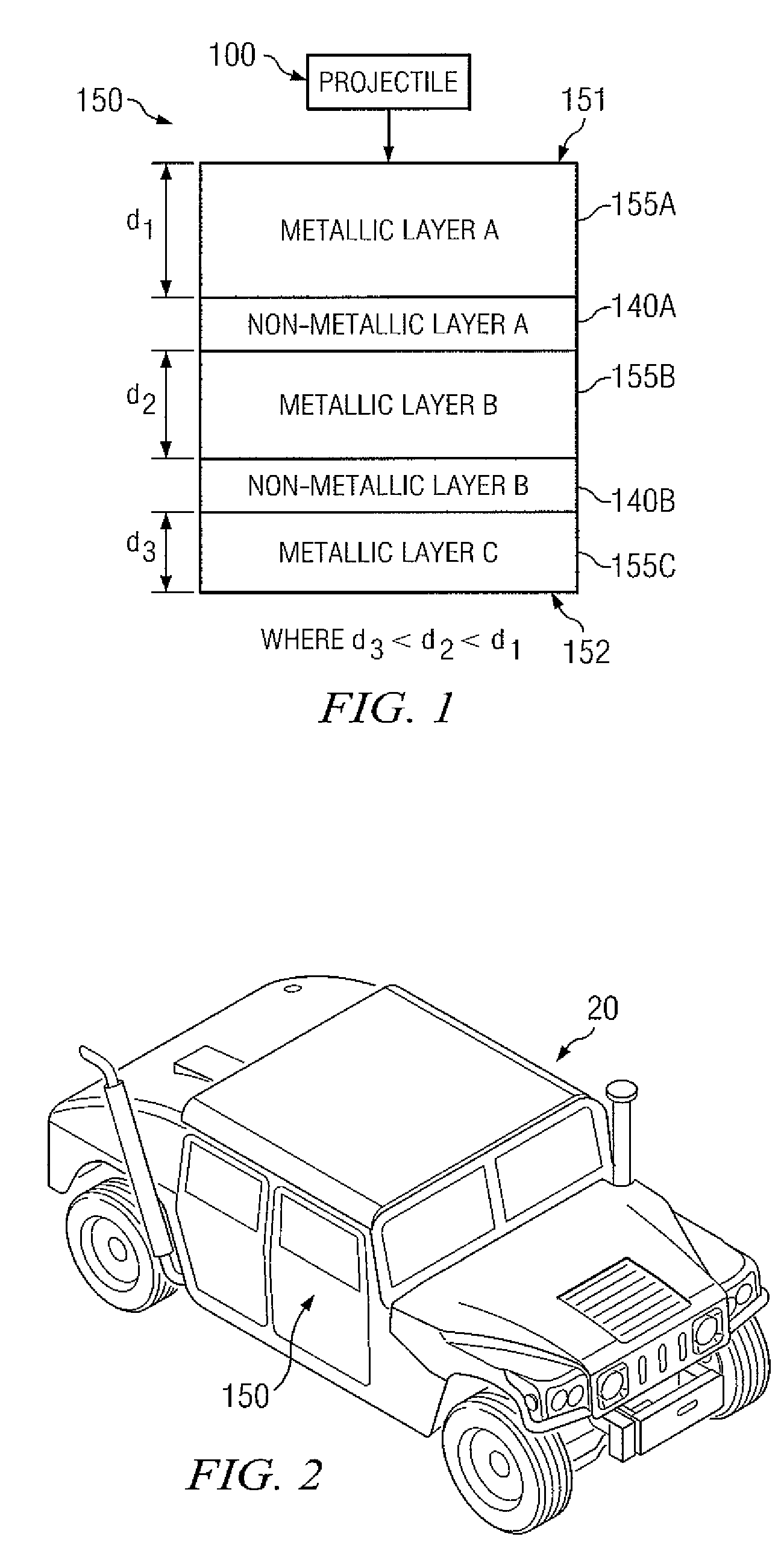
The patent describes an armor system made of multiple layers of metallic and non-metallic layers. The non-metallic layers are located in between the metallic layers and are designed to absorb impact and slow down particles of a projectile. The armor system is lighter and less expensive than conventional armor and can protect against a variety of projectiles and high velocity impacts. The technical effects of the invention include the ability to add a tumble to the path of a projectile, change the trajectory of a projectile, slow down particles of a projectile, withstand and resist multiple impacts from particles of a projectile, increase impact time, decrease the force exerted on armor layers, decrease the overall impact of a projectile, and provide protection against a shape charge.

Problems solved by technology

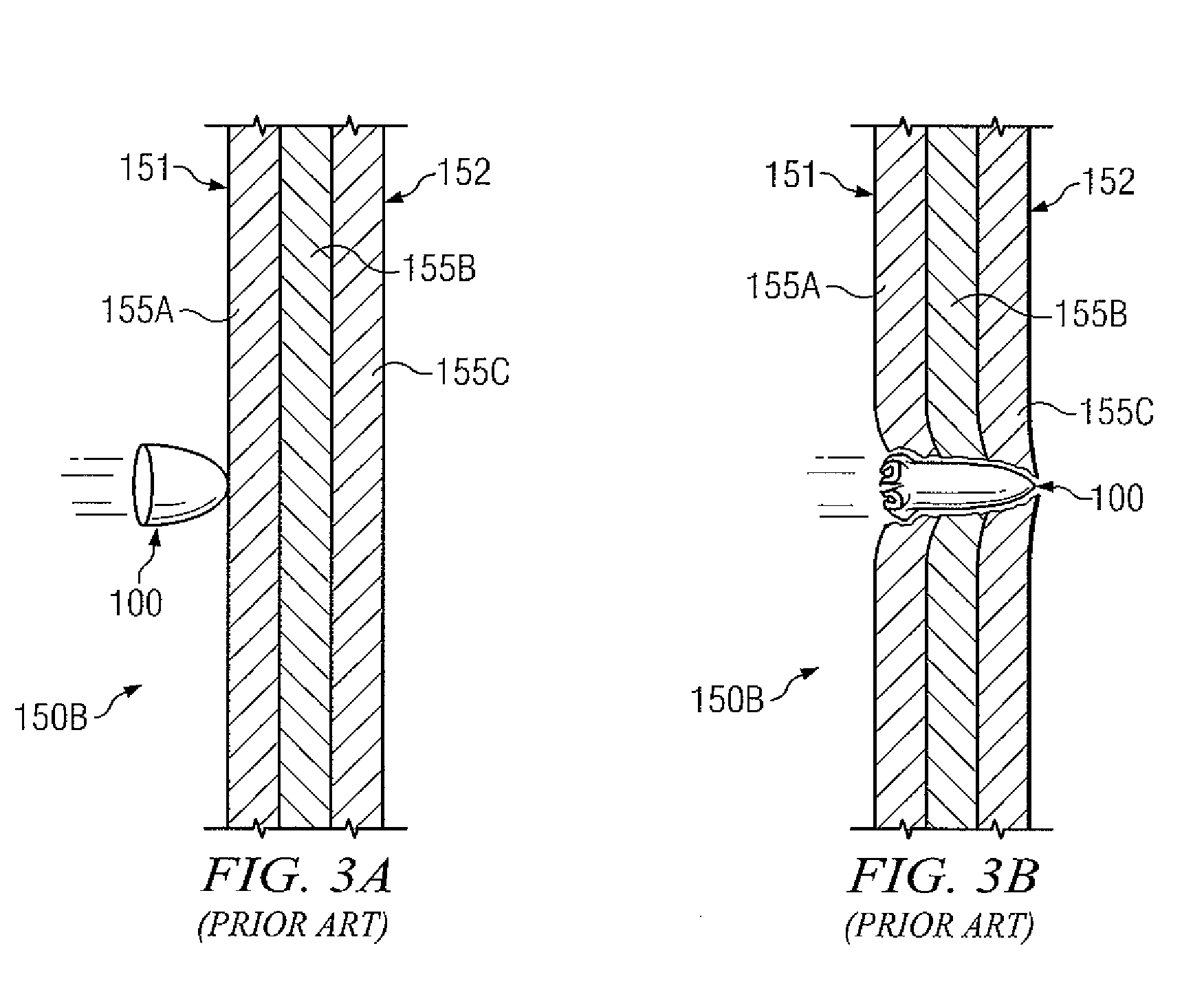
Improvised Explosive Devices (IEDs) and shape charges such as Explosively Formed Penetrators (EFPs) have accounted for a large number of combat casualties.
Despite focused efforts on armor development, Mine Resistant Ambush Protected (MRAP) vehicles and other armored vehicles still cannot defend against these threats.
However, these armor solutions typically weigh around 200 lb / ft2.
Since nearly all army vehicles are thousands of pounds overweight, even without any additional armor protection solution, most of these approaches have proved impractical.

Method used


Image

  • Layering non-metallic layers between metallic layers to improve armor protection
  • Layering non-metallic layers between metallic layers to improve armor protection
  • Layering non-metallic layers between metallic layers to improve armor protection

Examples


Embodiment Construction

[0014]It should be understood at the outset that, although example implementations of embodiments of the invention are illustrated below, the present invention may be implemented using any number of techniques, whether currently known or not. The present invention should in no way be limited to the example implementations, drawings, and techniques illustrated below. Additionally, the drawings are not necessarily drawn to scale.

[0015]Teachings of certain embodiments recognize that armor systems may be used to provide protection against and / or reduce impact of various projectiles such as but not limited to shaped charges, explosively formed penetrators (EFPs), IEDs, ballistic devices, other explosives and hypervelocity impacts. Armor systems of the disclosure may be used in conjunction with any vehicle, such as but not limited to, military vehicles, convoy vehicles and / or personnel carriers and may be useful to protect personnel and equipment in war zones.

[0016]On the battlefield, sha...


PUM

PropertyMeasurementUnit
thickaaaaaaaaaa
velocityaaaaaaaaaa
thicknessaaaaaaaaaa

Abstract

According to one embodiment, an armor system comprises a plurality of metallic layers. The armor system further comprises a plurality of non-metallic layers located in between two or more metallic layers of the plurality of metallic layers, such that each non-metallic layer is located at a respective depth in the plurality of metallic layers.

Description

TECHNICAL FIELD[0001]This invention relates generally to the field of armor systems and more specifically to light weight armor systems comprising layering non-metallic layers between metallic layers to protect against shape charges (e.g., an explosively formed penetrator (EPP)), other explosive devices, hypervelocity impacts and / or ballistic devices.BACKGROUND[0002]Improvised Explosive Devices (IEDs) and shape charges such as Explosively Formed Penetrators (EFPs) have accounted for a large number of combat casualties. Lethality of EFPs comes in part from the shape and arrangement of a concave copper cone, called the liner, which transforms into a forceful jet of fluidic metal which easily perforates steel armor. Despite focused efforts on armor development, Mine Resistant Ambush Protected (MRAP) vehicles and other armored vehicles still cannot defend against these threats. More recently, armor solutions such as the FRAG Kit 5 have been used to protect military vehicles such as Humv...

Claims


Application Information

Patent Timeline
Patent Type & Authority Patents(United States)
IPC IPC(8): F41H5/04
CPCF41H5/0457
Inventor ST. CLAIRE, ALEXANDER F.IMHOLT, TIMOTHY J.
Owner RAYTHEON CO
Learn More