Valve actuator assembly and methods of using the same

Active Publication Date: 2013-01-01
TRI TEC MFG
View PDF31 Cites 93 Cited by
  • Summary
  • Abstract
  • Description
  • Claims
  • Application Information

AI Technical Summary

Benefits of technology

[0024]The valve actuator assembly can move the valve between an open position and a closed position using a variable force based, at least in part, on the at least one signal from the sensor

Problems solved by technology

The replacement controller can operate the valve without performing a traditional calibration process, which is a ti

Method used


Image

  • Valve actuator assembly and methods of using the same
  • Valve actuator assembly and methods of using the same
  • Valve actuator assembly and methods of using the same

Examples


Embodiment Construction

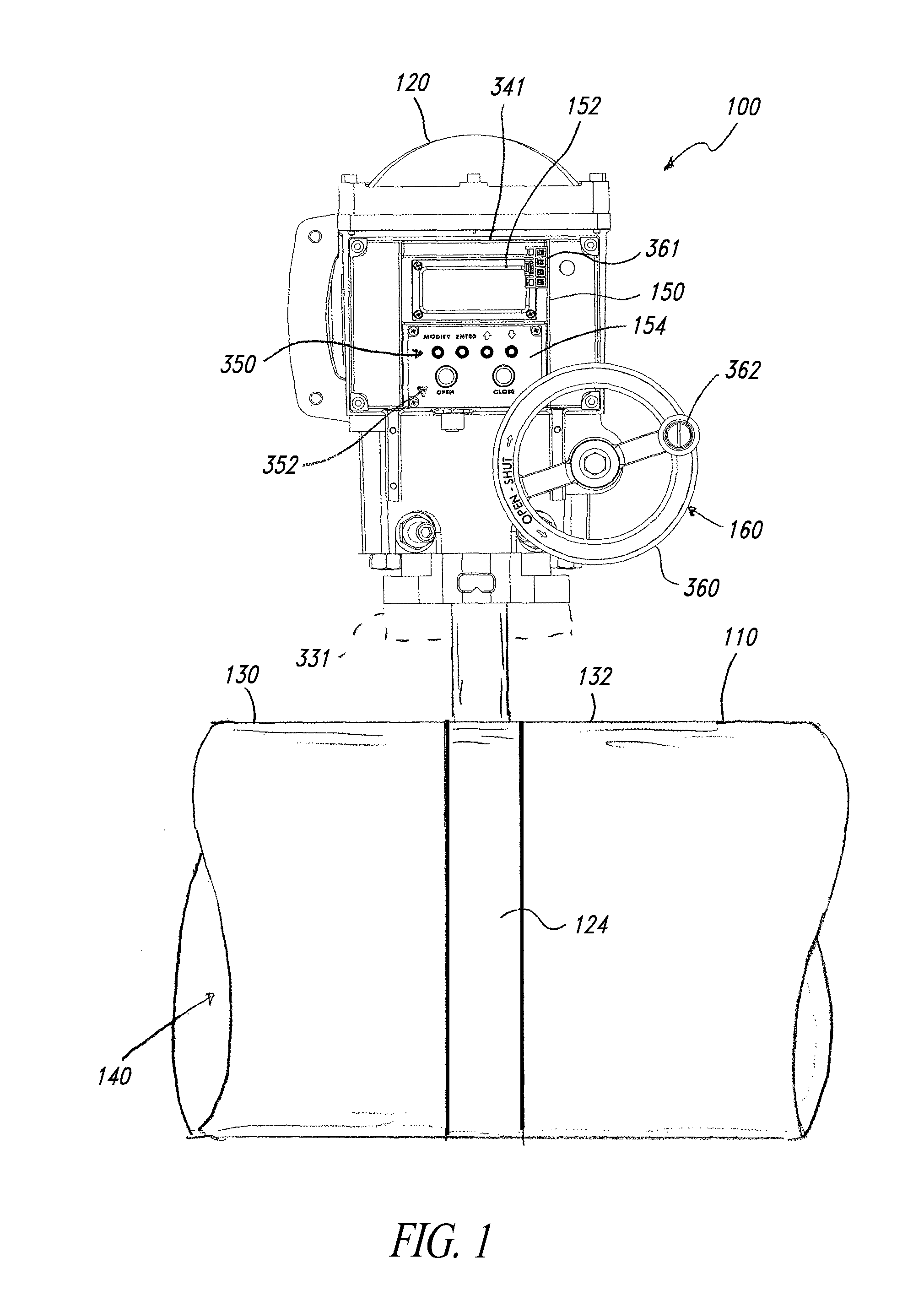
[0051]FIG. 1 shows a valve system 100 positioned along a conduit 110. The valve system 100 includes a valve actuator assembly 120 coupled to a valve 124 positioned between two sections 130, 132 of the conduit 110. The valve actuator assembly 120 operates the valve 124, which in turn regulates the flow of substances through the conduit 110. For example, the valve actuator assembly 120 opens the valve 124 to allow fluid flow along a passageway 140 of the conduit 110. To halt the fluid flow, the valve actuator assembly 120 closes the valve 124.

[0052]The valve actuator assembly 120 includes an electric controller 150 for automatically controlling the operation of the valve 124. The controller 150 includes a display 152 for displaying information to a user and manual input device 154 for inputting data. In one embodiment, the valve actuator assembly 120 further includes a hand wheel assembly 160 for operating the valve 124 without employing the controller 150. In this embodiment, the han...


PUM


Abstract

Valve systems include a valve and a valve actuator assembly for operating the valve. The valve actuator assembly includes a controller that uses stored information and signals from a sensor to open and close the valve. The controller can manipulate, analyze, evaluate, store, and communicate information related to the history of the valve, performance of the valve, valve settings, and the like. The controller can send information to a replacement controller or a replacement valve actuator assembly. Various types of wired and wireless connections can establish communication between the controller and the replacement controller or replacement valve actuator assembly.

Description

CROSS-REFERENCES TO RELATED APPLICATIONS[0001]This application claims the benefit under 35 U.S.C. §119(e) of U.S. Provisional Patent Application No. 61 / 061,971 filed Jun. 16, 2008; and U.S. Provisional Patent Application No. 61 / 102,276 filed Oct. 2, 2008. These provisional applications are incorporated herein by reference in their entireties.BACKGROUND[0002]1. Technical Field[0003]The present disclosure generally relates to valve actuator assemblies, more particularly, to valve actuator assemblies for use in a marine environment and methods of using the same.[0004]2. Description of the Related Art[0005]Valve actuators are often used to open and close valves positioned along pipes. Electric valve actuators can be used in a wide range of settings, including in waste water treatment plants, refineries, power plants, factories, and transportation vehicles, such as watercraft. Based on the ambient environment, components of electric valve actuators can be corrosion resistant, temperature...

Claims


Application Information

Patent Timeline
IPC IPC(8): F16K31/02
CPCF16K37/0075F16K31/055Y10T137/8242
Inventor CORDRAY, RICHARD L.KREMER, LESLIE A.BUSS, JACK
Owner TRI TEC MFG
Why Eureka
Try Eureka