Use of beam deflection to control an electron beam wire deposition process

a technology of electron beam wire and electron beam, which is applied in the direction of electro-beam welding apparatus, metal-working apparatus, welding apparatus, etc., can solve the problems of increasing control processing complexity, transient instability and discontinuities of deposited materials, and less than optimal conventional electron beam control methodologies for certain purposes

Active Publication Date: 2013-01-01
NASA
View PDF20 Cites 15 Cited by
  • Summary
  • Abstract
  • Description
  • Claims
  • Application Information

AI Technical Summary

Benefits of technology

[0006]Accordingly, a control method and apparatus are set forth herein for an electron beam process, e.g., electron beam welding and electron beam freeform fabrication (EBF3). The method, which is executable via the control apparatus set forth herein, provides for complex rastering of an electron beam generated in a vacuum, such as the chamber of an electron beam gun, and enables several processing functions or tasks to be performed simultaneously in parallel rather than in series. Thermal input into the EBF3 process results in self-correcting control and steering of a wire with respect to a molten pool formed during the process.
[0007]The present invention contemplates a splitting of the duty cycle of the electron beam during rastering. This in turn enables real-time control of electron beam processing, along with the simultaneous achievement of multiple tasks or objectives. Process control is thus optimized at lower relative power consumption levels while minimizing undesirable process issues, e.g., selective vaporization of low vapor pressure alloying elements, thermal residual stress, and distortion, associated with excessive thermal input into components during electron beam processing. Beam rastering as set forth herein may dramatically reduce the number of flaws encountered, particularly during EBF3. The method uses beam deflection to preheat and steer the wire into the molten pool, thus reducing a primary flaw source when the wire exits the pool.
[0008]The self-corrective method provides for control over the location, power, and dwell time of the electron beam to generate a complex raster pattern, and uses the raster pattern to control thermal input and distribution. The raster pattern redirects the wire, and retains a position of the wire with respect to the molten pool by focusing the beam on the outside of the wire. This selectively heats the outer edges of the wire, and prevents straying of the wire from the molten pool. The method is “self-correcting” in that it maintains the wire in the pool without requiring sensing or external changes to the raster pattern or wire orientation.

Problems solved by technology

Conventional electron beam control methodologies may be less than optimal for certain purposes, such as for maintaining an even or consistent material deposition height.
Perturbations may cause the wire to stray from the beam path and / or the molten pool, potentially causing transient instability and discontinuities in the deposited material.
With the development of EBF3, control processing complexity has increased dramatically.

Method used


Image

  • Use of beam deflection to control an electron beam wire deposition process
  • Use of beam deflection to control an electron beam wire deposition process
  • Use of beam deflection to control an electron beam wire deposition process

Examples


Embodiment Construction

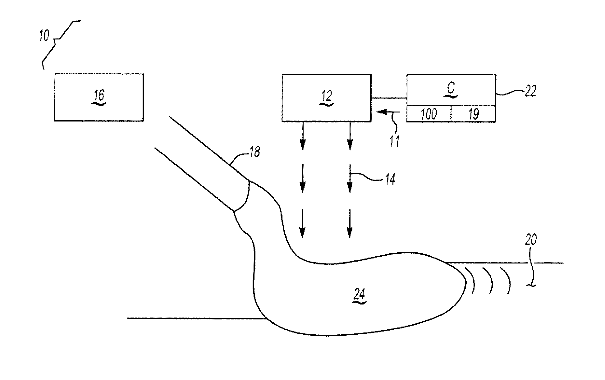
[0016]Referring to the drawings wherein like reference numbers represent like components throughout the several figures, and beginning with FIG. 1, an apparatus 10 is configured for forming a product using an electron beam 14. Such a process may include beam welding, or, in another embodiment, may include electron beam freeform fabrication, hereinafter abbreviated as EBF3 for simplicity. The apparatus 10 includes an electron beam gun 12 adapted to generate the electron beam 14. While the electron beam 14 is shown external to the electron beam 12 for clarity, those of ordinary skill in the art will recognize a vacuum chamber (not shown) is present within which the electron beam 14 is ultimately generated and contained.

[0017]The apparatus 10 includes a wire feeder 16 adapted for feeding a length of consumable wire 18 toward a substrate 20, and a controller (C) 22. The substrate 20 may be positioned on a moveable platform (not shown), with the platform and / or the gun 12 being movable v...


PUM

PropertyMeasurementUnit
poweraaaaaaaaaa
dwell timeaaaaaaaaaa
temperature distributionaaaaaaaaaa

Abstract

A method for controlling an electron beam process wherein a wire is melted and deposited on a substrate as a molten pool comprises generating the electron beam with a complex raster pattern, and directing the beam onto an outer surface of the wire to thereby control a location of the wire with respect to the molten pool. Directing the beam selectively heats the outer surface of the wire and maintains the position of the wire with respect to the molten pool. An apparatus for controlling an electron beam process includes a beam gun adapted for generating the electron beam, and a controller adapted for providing the electron beam with a complex raster pattern and for directing the electron beam onto an outer surface of the wire to control a location of the wire with respect to the molten pool.

Description

CROSS-REFERENCE TO RELATED APPLICATIONS[0001]This application claims priority to and the benefit of U.S. Provisional Application 61 / 173,292, filed on Apr. 28, 2009, which is hereby incorporated by reference in its entirety. In addition, this application is co-pending with the related application entitled “CLOSED-LOOP PROCESS CONTROL FOR ELECTRON BEAM FREEFORM FABRICATION AND DEPOSITION PROCESSES,” U.S. application Ser. No. 12 / 750,991, filed on the same day and owned by the same assignee as this application, the contents of which are incorporated herein by reference in their entirety.ORIGIN OF THE INVENTION[0002]This invention was made in part by employees of the United States Government and may be manufactured and used by or for the Government of the United States of America for governmental purposes without the payment of any royalties thereon or therefor.TECHNICAL FIELD[0003]The present invention relates to a method and apparatus for controlling a beam position during an electron ...

Claims


Application Information

Patent Timeline
Patent Type & Authority Patents(United States)
IPC IPC(8): B23K15/00
CPCB23K15/02
Inventor TAMINGER, KAREN M.HOFMEISTER, WILLIAM H.HAFLEY, ROBERT A.
Owner NASA
Why Eureka
Try Eureka