Device for nondestructive testing of pipes

a non-destructive testing and pipe technology, applied in the direction of instruments, magnetic measurements, transducer types, etc., can solve the problems of complex and expensive test systems, high cost, and high labor intensity, and achieve the effect of reducing labor intensity, reducing labor intensity, and improving labor intensity

Inactive Publication Date: 2013-01-01
V&M DEUT GMBH
View PDF8 Cites 9 Cited by
  • Summary
  • Abstract
  • Description
  • Claims
  • Application Information

AI Technical Summary

Benefits of technology

[0016]With the present invention, inductive sensors are replaced with GMR sensors, which have an enormous potential for improving the informative value of tests by, for example, increasing the reliability, offering the possibility to test greater wall thicknesses, improving signal evaluation due to better sensor arrangement, while substantially reducing of electronic and mechanical complexity, primarily by reducing the complexity of the test head compared to a conventional GMR test head which in general employs a dedicated preamplifier for each sensor.
[0017]Several GMR sensors can be directly electrically connected in parallel in form of an array. This eliminates the aforementioned disadvantages associated with the complex sensor electronics for each individual sensor in conventional designs.
[0019]This design can optimize the spatial resolution and reduce the complexity of the components.
[0020]In another advantageous embodiment of the invention, gaps in testing which can be caused by a spatial separation of the sensors, can be reliably prevented by arranging adjacent sensor groups in such a way so that at least one sensor in one group overlaps with a sensor in the other group.

Problems solved by technology

Magnetic and magnetic-induction test procedures, for example the conventional magnetic leakage flux test, are used with pipes made of ferromagnetic steel to detect, in particular, longitudinal, transverse or inclined discontinuities, for example cracks, near the surface which cannot be detected at all or only with great imprecision with other test procedures, which tend to be expensive and time-consuming.
The test system consequently becomes quite complicated and expensive.
The use of a dedicated preamplifier for each GMR sensor necessitates a large number of components and connections.
This complexity is necessary, in particular, if the increased lateral resolution is taken advantage of.
Disadvantageously, the overall dimensions of the test unit increase substantially, which may cause problems in confined spaces.
Due to the small size of the sensors, it is difficult to install this large number of connections in the test head.

Method used


Image

  • Device for nondestructive testing of pipes
  • Device for nondestructive testing of pipes
  • Device for nondestructive testing of pipes

Examples


Embodiment Construction

[0028]Throughout the Figures, same or corresponding elements are generally indicated by same reference numerals. These depicted embodiments are to be understood as illustrative of the invention and not as limiting in any way. It should also be understood that the drawings are not necessarily to scale and that the embodiments are sometimes illustrated by graphic symbols, phantom lines, diagrammatic representations and fragmentary views. In certain instances, details which are not necessary for an understanding of the present invention or which render other details difficult to perceive may have been omitted.

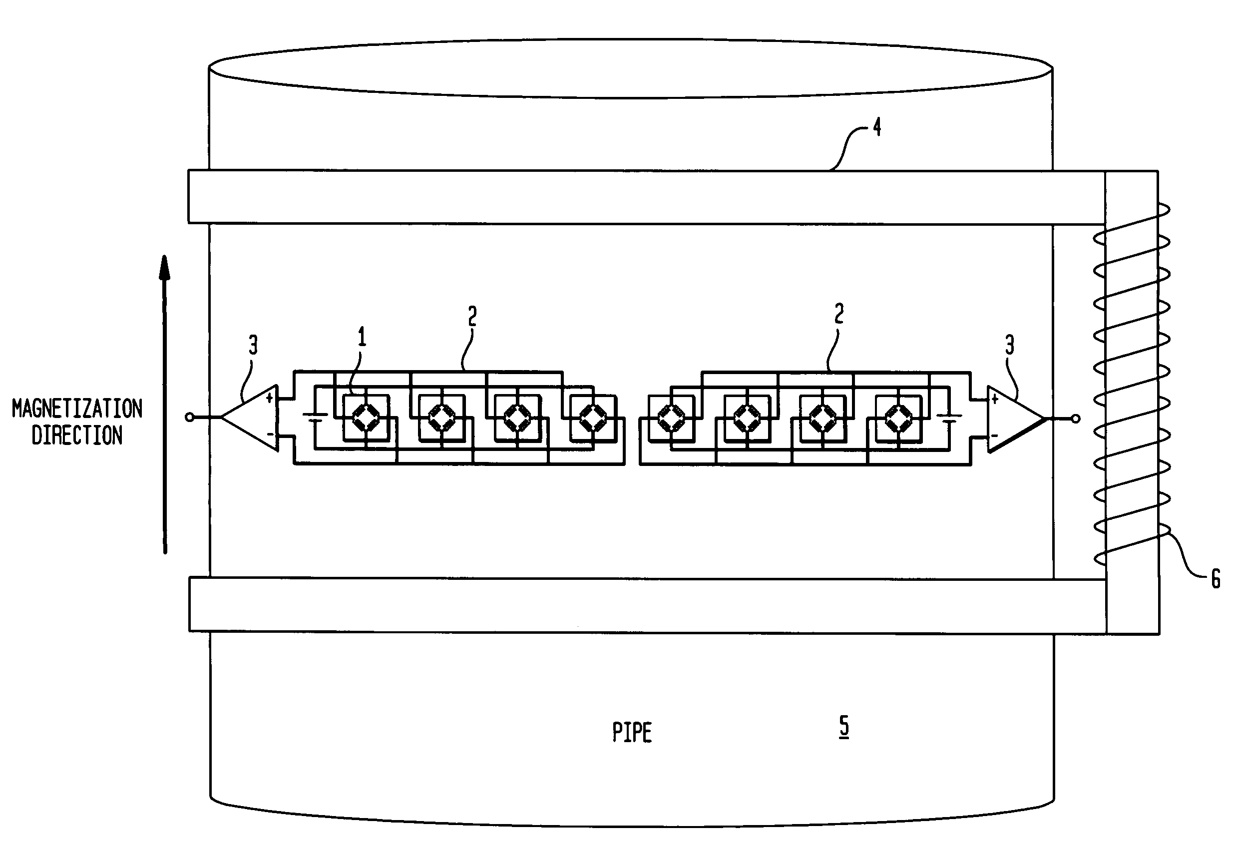
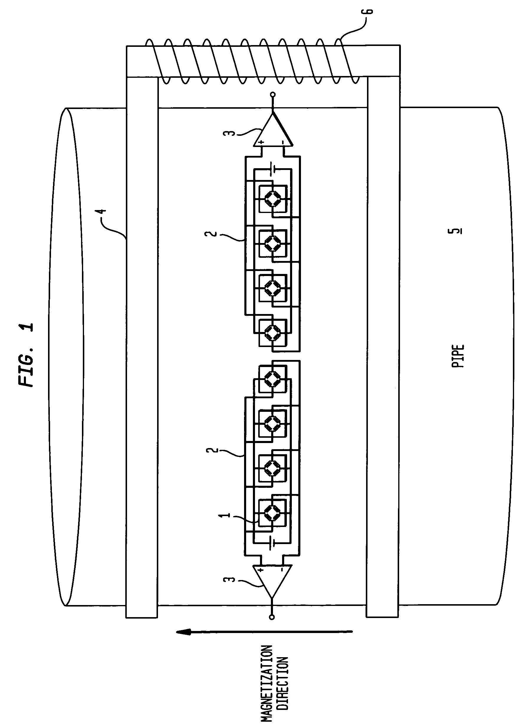
[0029]Turning now to FIG. 1, there is shown a first exemplary embodiment of an array 2 formed from a combination of GMR sensors 1 electrically connected in parallel according to the invention. The arrow shows the magnetization direction which may coincide with the testing direction of the pipe 5. A magnetizing yoke 4 transmits the magnetic flux, which may be generated by a coil 6 ...


PUM

PropertyMeasurementUnit
magneticaaaaaaaaaa
magnetic-induction testaaaaaaaaaa
magnetic fluxaaaaaaaaaa

Abstract

A device for nondestructive testing of a pipe made of ferromagnetic steel for detection of longitudinal, transverse or inclined flaws using magnetic or magnetic-induction test procedures is disclosed. The device includes a magnetizing yoke which transmits the magnetic flux contactless into the pipe and at least two magnetic-field-sensitive scanning probes having GMR sensors. The GMR sensors are combined into sensor groups in form of a sensor array and electrically connected in parallel. A single preamplifier connected to each sensor group in one-to-one correspondence. The device further includes an evaluation unit.

Description

CROSS-REFERENCES TO RELATED APPLICATIONS[0001]This application claims the priority of German Patent Application, Serial No. 10 2009 010 453.4, filed Feb. 26, 2009, pursuant to 35 U.S.C. 119(a)-(d), the content of which is incorporated herein by reference in its entirety as if fully set forth herein.BACKGROUND OF THE INVENTION[0002]The invention relates to a device for nondestructive testing of pipes made of ferromagnetic steel using magnetic or magnetic-induction test procedures.[0003]Devices of this type have of a magnetizing yoke which transmits the magnetic flux contactless into the pipe and at least two magnetic-field-sensitive scanning probes implemented as GMR sensors as well as an evaluation unit.[0004]Magnetic and magnetic-induction test procedures, for example the conventional magnetic leakage flux test, are used with pipes made of ferromagnetic steel to detect, in particular, longitudinal, transverse or inclined discontinuities, for example cracks, near the surface which c...

Claims


Application Information

Patent Timeline
Patent Type & Authority Patents(United States)
IPC IPC(8): G01N27/82
CPCG01N27/82
Inventor FISCHER, GERTGWILDIES, SVENKAACK, MICHAELGRAFF, ALFREDKOKA, ASHRAFNITSCHE, STEFAN
Owner V&M DEUT GMBH
Why Eureka
Try Eureka