Detecting contacts during sporting activities etc

a technology for detecting contacts and sporting activities, applied in the field of detecting contacts during sporting activities etc., can solve problems such as system limitations, obvious dislocation, and affecting the validity of calls made by umpires and linesmen

Inactive Publication Date: 2013-01-08
BRENNAN BROADCAST GRP PTY LTD
View PDF18 Cites 11 Cited by
  • Summary
  • Abstract
  • Description
  • Claims
  • Application Information

AI Technical Summary

Benefits of technology

[0022]It is an object of the present invention to provide methods and apparatus for determining parameters of contact occurring within an activity and which can provide at least a useful alternative to other systems aimed generally at performing similar functions.
[0032]The step of comparing image data to detect a localised infra red emission may be performed automatically, particularly by execution of an appropriate algorithm by programmed processing means so as to identify the incident frame. The incident frame, or perhaps the frame automatically detected as being the most probable incident frame of interest (e.g. the one having the pixel with the highest value of infra red emission) may then be automatically, or selectively in response to user command, displayed on the visual display means as the relevant captured image of the target area. In one possible embodiment, the process may include the further step of selecting an incident zone within the image of the target area for the displayed incident frame, the incident zone being a selected area within the displayed image in which the localised infra red omission of interest is identified. Preferably the process then includes the further step of further processing the image data for pixels within tee selected incident zone to enhance in the image presented by the visual display means the visibility of the infra red emission sources in the captured image. For example, the image data for pixels within the selected incident zone may be processed, e.g. by a digital filtering operation, to enhance the contrast or brightness of pixels having a relatively high infra red emission value compared to nearby pixels. Software for enhancing contrast or brightness is known and commonly provided with picture or image processing software. The selection of the incident zone from within tee displayed image may be carried out for example by a user operating an interface device such as a computer mouse to select the area of the displayed image where the localised IR emission of interest is identified by the user inspecting the display. For example, a curser on the displayed image can be positioned at the image of the IR emission and, upon the user clicking upon that point, the associated software can then automatically enhance the visibility of the IR emission source by enhancing contrast or brightness for the selected pixel and preferably for numerous nearby or contiguous pixels, or for pixels having relatively high IR emission values at, adjacent and / or surrounding the selected point, As an alternative to positioning a curser at a single point, a box may be drawn around the display image area where the localised IR emission of interest is identified, e.g. by positioning a curser and then dragging across the area of interest to create a box constituting the selected area, and the filtering to brighten or increase contrast can be performed only on data for pixels within the box. For example, the filtering can increase contrast of those pixels that have beat values within say 2% of the maximum heat value.
[0033]Another step of the process that may be performed in a preferred embodiment comprises enhancing the displayed images to enable better user discrimination of features in captured images of the target area. Apart from the enhancement of the IR emissions discussed above, another useful enhancement may comprise image data processing to increase contrast and / or brightness of playing area features such as lines on a tennis court. When a tennis court is in deep shade the IR emission differences between lighter more reflective (and hence cooler) lines and surrounding court surfaces can reduce to make visual discrimination of lines in the displayed image. Upon user selecting e.g. by positioning a cursor on a known image section representing a court line marking, and upon clicking thereon, the processor may filter all data for that image to enhance brightness of all pixels having a substantially identical IR heat value to the selected pixel, say within 2% of that heat value. This will brighten the court making lines in the displayed image.
[0034]Another process to enhance visibility and / or automatic determination of relevant non-IR emission sources such as tennis court line markings may comprise filtering to enhance image data for a particular part of the visible spectrum. For example, line markings may incorporate say a yellow or orange reflective component and a filtering process may be performed to increase the brightness count for this part of the spectrum in the captured images, thereby enhancing visibility of the line markings in a displayed image and / or improving the accuracy of image analysis software to automatically discriminate the line markings.

Problems solved by technology

There is much dissension evident in tennis tournaments concerning the validity of calls made by the umpire and lines persons.
These systems can have one or more limitations such as expense of the hardware systems and installations thereof; the difficulty and precision required in providing calibrating or testing and operating of such systems at a tennis venue; limitations on applicability throughout a tennis game since there can be many movements of bodies and many impacts on the court surface during a tennis game that can be registered by such apparatus and, unless accurately discriminated, could lead to false indications—for example the “Cyclops” system is generally used only for determining the bounce point of a tennis player's serve and not subsequent tennis shots.

Method used


Image

  • Detecting contacts during sporting activities etc
  • Detecting contacts during sporting activities etc
  • Detecting contacts during sporting activities etc

Examples


Embodiment Construction

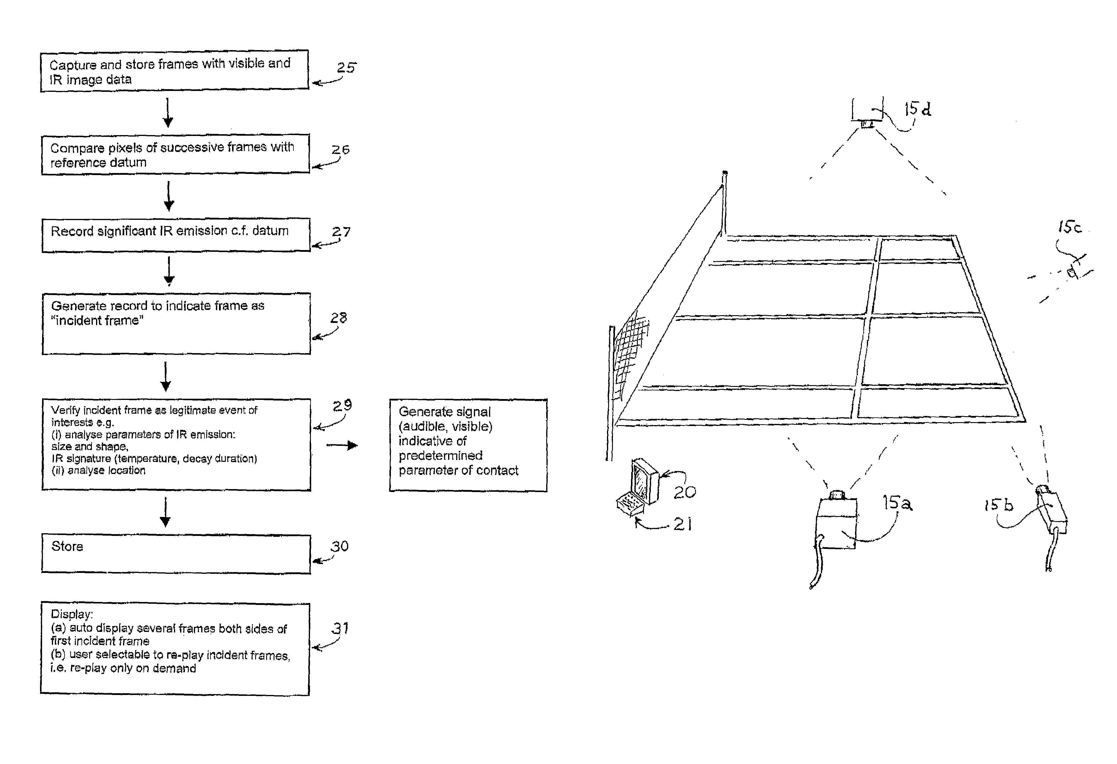
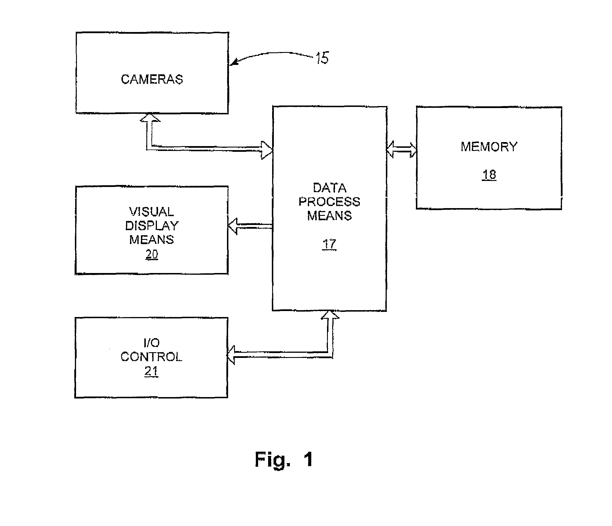
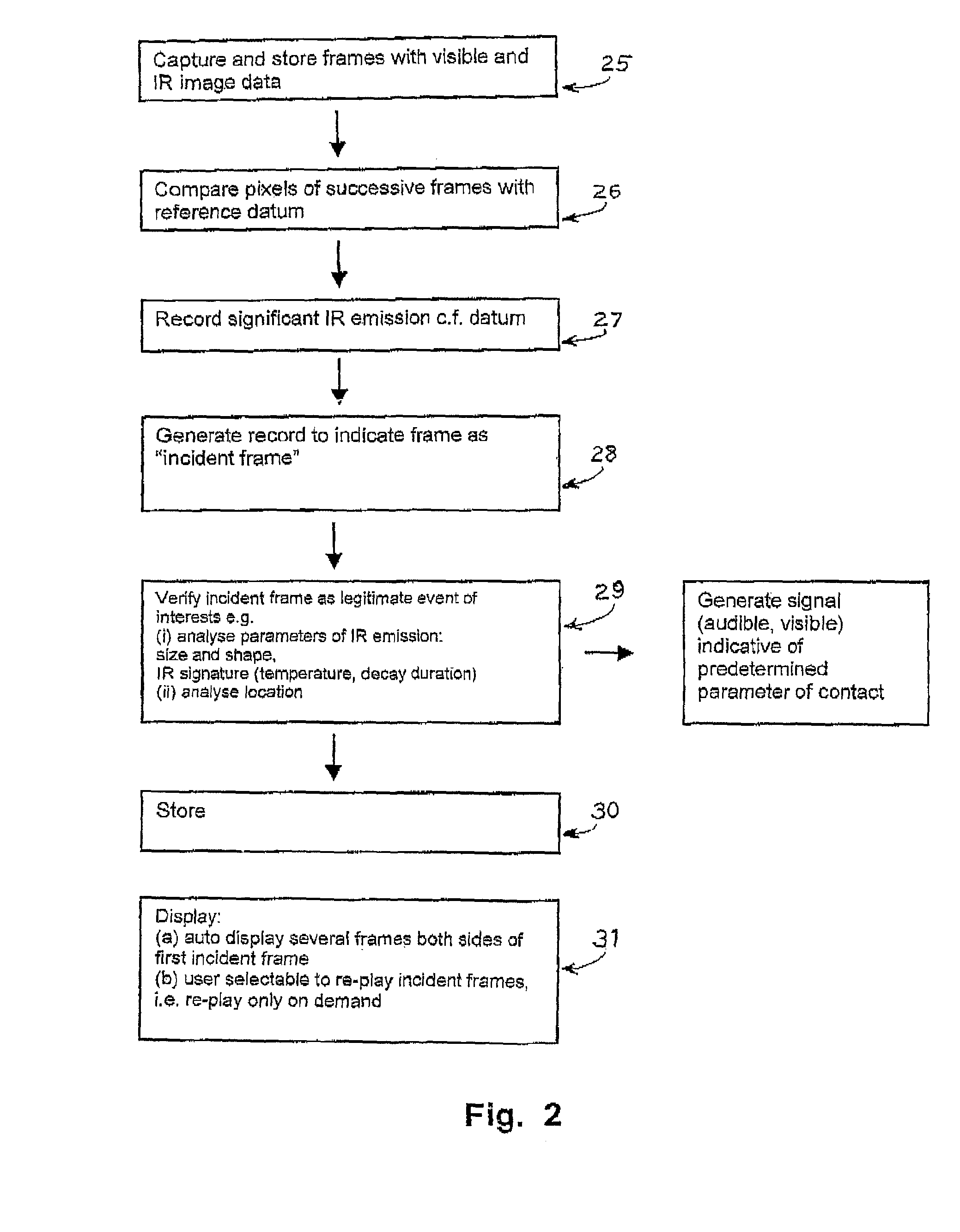
[0076]The apparatus in FIG. 1 includes one or more digital cameras 15 directed in use towards a target area such as a sporting, game, recreational, or entertainment area, or area where an activity is to be undertaken. Camera 15 need not be fixed in location but could be movable by an operator, and indeed could be hand held since the process and operations of the invention can be performed provided the camera is directed to the target area when the particular contact incident of interest occurs. The camera could be a digital “still” camera operated to capture an image of the target area shortly after the contact of interest occurs. However for most purposes the implementation of the invention will involve at least one digital video camera which in use is mounted in a known location and is directed towards a respective target area during the course of the activity so as to capture image frames of the target area. A camera capturing frames at 92 frames per second has been successfully ...


PUM


Abstract

A method and an apparatus are described for determining parameters of a contact between bodies occurring within an activity. A digital camera directed towards a target area during the activity captures image frames including infra red image data. Structure for comparing image data for multiple temporally spaced frames with image data of a reference datum records any localized infra red emission appearing in at least one incident frame. The image data for at least one of the incident frames is analyzed to determine at least one parameter of the contact, and the image data for the incident frame is recorded. Visual display means displays the incident frames including the image data in the IR spectrum to enable visual inspection of the activity in the target area at the time of the incident frame and that gave rise to the contact producing the infra red emission.

Description

CROSS REFERENCE TO RELATED APPLICATION[0001]This application relates to the same general subject matter as AU innovation patent No. 2006100154 and AU patent application 2006906528 and the entire contents of the specifications of those patents are incorporated herein by this cross reference.BACKGROUND[0002]1. Field of the Invention[0003]This invention relates to determining the existence and / or a property (such as the location) of a contact such as a ball bounce in a sporting activity or the like.[0004]2. Background of the Invention[0005]The invention has been particularly developed for determining the location of the bounce point of a tennis ball in relation to the court line markings so as to enable objective determination whether the preceding tennis stroke has complied with the rules of tennis or whether the point of bounce is outside of the relevant court lines. The invention, however, is not limited to this particular field of application. For example the invention can be used ...

Claims


Application Information

Patent Timeline
Patent Type & Authority Patents(United States)
IPC IPC(8): A63F13/12
CPCA63B24/0003A63B24/0021A63B69/00A63B71/0605A63B2024/0025A63B2071/0625A63B2220/05A63B2220/13A63B2220/806A63B2220/807A63B2243/0037A63B2243/0095A63B2244/102A63B2244/22A63B2102/02A63B2102/18A63B2102/182A63B2102/20G09B19/0038H04N5/33A63B71/06
Inventor BRENNAN, WARREN
Owner BRENNAN BROADCAST GRP PTY LTD
Why Eureka
Try Eureka