Ultra-wideband antenna element and array

Active Publication Date: 2013-01-08
THE UNITED STATES OF AMERICA AS REPRESENTED BY THE SECRETARY OF THE NAVY
View PDF8 Cites 27 Cited by
  • Summary
  • Abstract
  • Description
  • Claims
  • Application Information

AI Technical Summary

Benefits of technology

[0007]The invention described here is an all-metal radiator with a direct coax feed, capable of handling high power. The invention provides a means of transferring energy directly from a coax or strip-line feed to a full-metal slot-line, without necessitating a quarter-wave stub, with excellent bandwidth and no soldering required.
[0008]The first advantage of the antenna element of the invention is that it achieves a higher bandwidth of operation than can usually be achieved. This makes it particularly appealing for applications that require a great deal of bandwidth, such as multi-function arrays. Because an array of this type can operate over such a large bandwidth, it is possible to use a single aperture for multiple functions/uses, rather than resorting to two or more independent arrays, as this requires greater installation space. UWB arrays become even more appealing when there is simply not the space for multiple arrays to be installed. In the prototype design, for broadside radiation, a 12:1 bandwidth is achieved (725 MHz to 8.9 GHz) with VSWR levels below 2 across the entire band. The element maintains VSWR well below 2 for scans out to 45 degrees in all scan planes over more than 8:1 bandwidth (850 MHz to 8.1 GHz). If VSWR levels of 3 are acceptable, this can be achieved from 800 MHz to 8.4 GHz, for more than 10:1 bandwidth. This operational frequency range is reported with the caveat that scanning may be somewhat restricted at the higher frequencies due to the half-wavelength element spacing of 7.4 GHz in the design shown. It is important to note that like most antenna structures, the operational frequency range changes with scaling the dimensions of the antenna.
[0009]The second advantage of the antenna element is that it is an all-metal design. Whereas most wideband Vivaldi arrays are constructed using printed circuit boards and thin metallization layers that cannot handle much power, this all-metal design is ideal for high-power applications. Though there are other all-metal designs in the literature, this design has the advantage that the antenna transitions energy directly from coax to slot-line with a direct short-circuit. The use of a single transition from coax to slot-line and the use of very wide bandwidth short-circuit transformer results in increased overall bandwidth and performance, and reduces standing waves/heating issues in the antenna feed chain.
[0010]The third advantage of the antenna element is that the feed inserts straight into the back of the element. In

Problems solved by technology

When condensed into an array configuration, another low-frequency limitation is introduced by the limited space for feed circuits.
It is difficult to design ultrawideband circuits that can fit in the constricted array element cell.
Ferrite-tuned feed circuits can potentially achieve high bandwidths, but cannot be used at microwave frequencies and above

Method used


Image

  • Ultra-wideband antenna element and array
  • Ultra-wideband antenna element and array
  • Ultra-wideband antenna element and array

Examples


Embodiment Construction

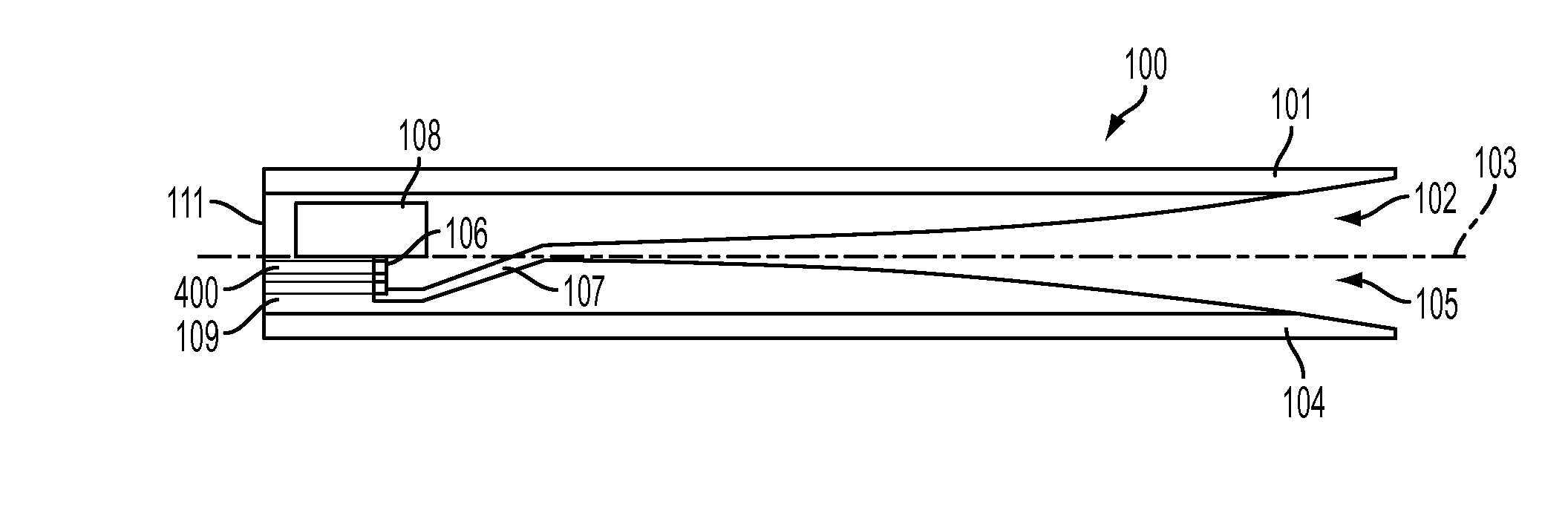
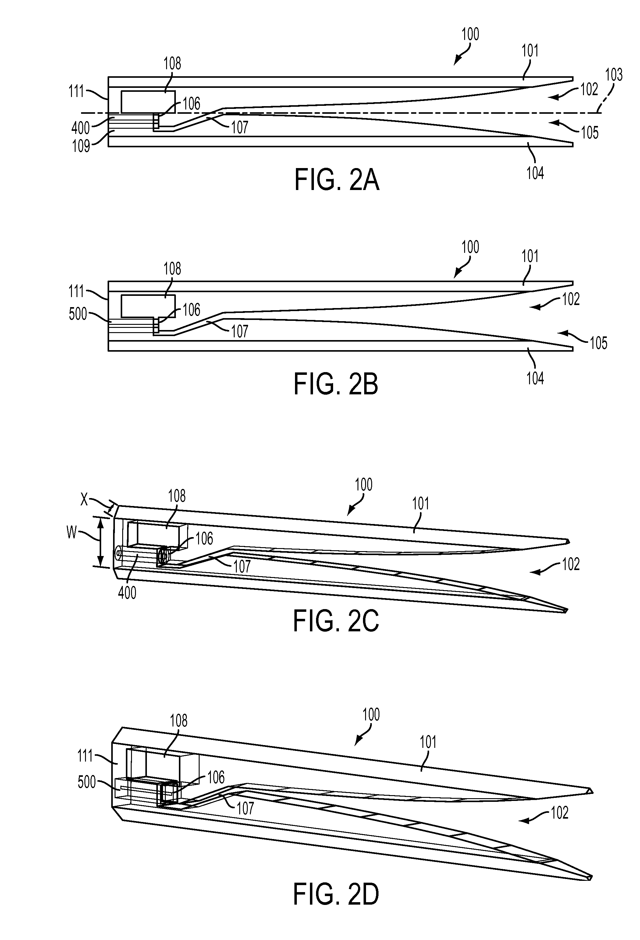
[0025]Definition(s): As used herein, and as is well understood in the subject technical field, the term “slot” is used interchangeably with “slot-line” when describing a Vivaldi-type antenna.

[0026]Referring now to FIGS. 2A-B, a Vivaldi-type antenna element 100 as in the invention is preferably all-metal and has a body 101 with a tapered slot 102 along a main axis 103, preferably its central axis, that at one end 104 has an outwardly flared opening 105 and that extends along axis 103 into a meandering portion 107 having an offset with respect to axis 103 and then into a second end 106 that has a sideways bend with respect to axis 103 and becomes a slot line open circuit or “open” where it terminates into a slot-line cavity 108, preferably at or near the center of the cavity 108 as shown. Cavity 108 functionally is more than merely a cavity per se, as it serves as a quarter-wave transformer that is also made larger than the slot to cause an impedance mismatch to further enhance the ba...


PUM


Abstract

An antenna element for fabricating into a linear or planar array includes a tapered slot along a main axis of the antenna element body that extends from a first slot end, defined by an outwardly flared opening at a second end of the antenna element, into a second meandering portion that is offset from the main axis, and then into a second slot end having a bend with respect to the main axis, and finally into a slot-line cavity proximate to the first end of the antenna element body. A feed port extends into the antenna element body from the outer surface of the first end of the antenna element body into the second slot end bend adjacent the slot-line cavity.

Description

CROSS-REFERENCE TO RELATED APPLICATIONS[0001]This Application claims the benefit of U.S. Provisional Application 61 / 183,618 filed on Jun. 3, 2009, and incorporated herein by reference.FIELD OF THE INVENTION[0002]The invention relates to an antenna element and array, and more particularly, to a Vivaldi-type or flared-notch antenna and array.BACKGROUND OF THE INVENTION[0003]A popular antenna element for ultra-wideband antenna arrays is the Vivaldi aerial (antenna), also commonly known as the tapered-slot or flared-notch antenna. As stand-alone antennas, Vivaldi aerials can exhibit ultra-wide bandwidths of operation, where the high frequency range is typically limited by the slot-width near the feed, and low frequency is typically dictated by the width of the overall taper (must be approximately at least half a wavelength), with the overall length of the taper in the direction of end-fire radiation typically several wavelengths long. They function in a slightly different manner when co...

Claims


Application Information

Patent Timeline
IPC IPC(8): H01Q13/10
CPCH01Q13/085H01Q5/55H01Q21/068
Inventor KINDT, RICKIE W.
Owner THE UNITED STATES OF AMERICA AS REPRESENTED BY THE SECRETARY OF THE NAVY
Why Eureka
Try Eureka