Supercharge Your Innovation With Domain-Expert AI Agents!

System and method for detecting interfernce in a sensor device using phase shifting

a sensor device and phase shifting technology, applied in the field of electronic devices, can solve the problems of long-standing difficulties in identifying and reducing the effects the effect of interference achieve the effect of reducing the effect of noise and other interferers on the sensor device, identifying and removing, and reducing the effect of interferen

Active Publication Date: 2013-01-08
SYNAPTICS INC
View PDF14 Cites 4 Cited by
  • Summary
  • Abstract
  • Description
  • Claims
  • Application Information

AI Technical Summary

Benefits of technology

The patent text describes a system and method for detecting interference in a capacitive sensor device. The system uses a carrier signal that is modulated in response to a stimulus and produces an output signal. The carrier signal is switched between multiple phases at a low frequency, which causes the interference in the output signal to spread in frequency around the effects of the user-applied stimulus. An interference detection filter filters out the interference and produces an interference output. The system can detect interference in the output of the capacitive sensor device, even when the interference is close in frequency to the user-applied stimulus. The method also includes shifting the carrier frequency to an alternate primary frequency when interference is detected and filtering out the interference. Overall, the system and method provide a way to accurately detect interference in signals from capacitive sensors and take appropriate action to reduce or eliminate the interference.

Problems solved by technology

One issue with some past proximity sensor devices is effects of interference on the sensor device.
In particular, difficulties have long been realized in identifying and reducing the effects of noise and other interferers upon the sensor device.
Although many sensors now include filtering that can effectively remove many types of interference, problems remain in identifying and removing interference with frequencies that are close to the sensor sensing frequency or any of its harmonics.
These types of interferers are sometimes referred to as “tuned noise”, and are difficult to identify or filter out.
As a result, distinguishing the effects of undesirable tuned noise from the desirable effects of the stimulus can be quite difficult.
Further, in some instances the beat signal may be indistinguishable from a user input.
This technique has several disadvantages, however, in that determining whether the stimulus is present at any given time can be difficult in practice, particularly in the presence of significant external interference.
Moreover, because this technique measures interference only when the stimulus is not present, sources of interference present within the stimulus itself (e.g. environmental radio frequency noise coupled to the sensor via the stimulus) are not considered.

Method used


Image

  • System and method for detecting interfernce in a sensor device using phase shifting
  • System and method for detecting interfernce in a sensor device using phase shifting
  • System and method for detecting interfernce in a sensor device using phase shifting

Examples


Embodiment Construction

[0016]The following detailed description is merely exemplary in nature and is not intended to limit the invention or the application and uses of the invention. Furthermore, there is no intention to be bound by any expressed or implied theory presented in the preceding technical field, background, brief summary or the following detailed description.

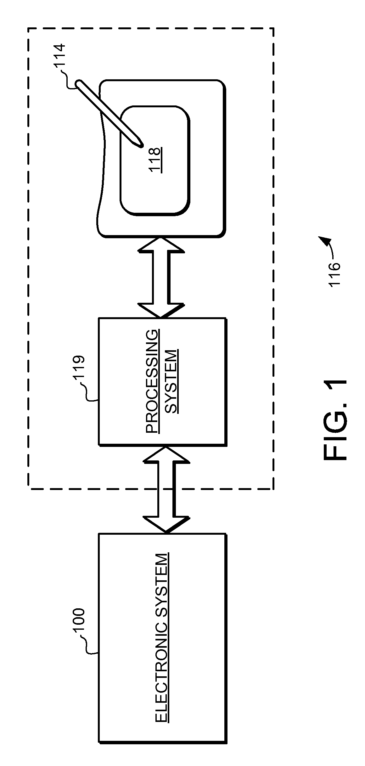
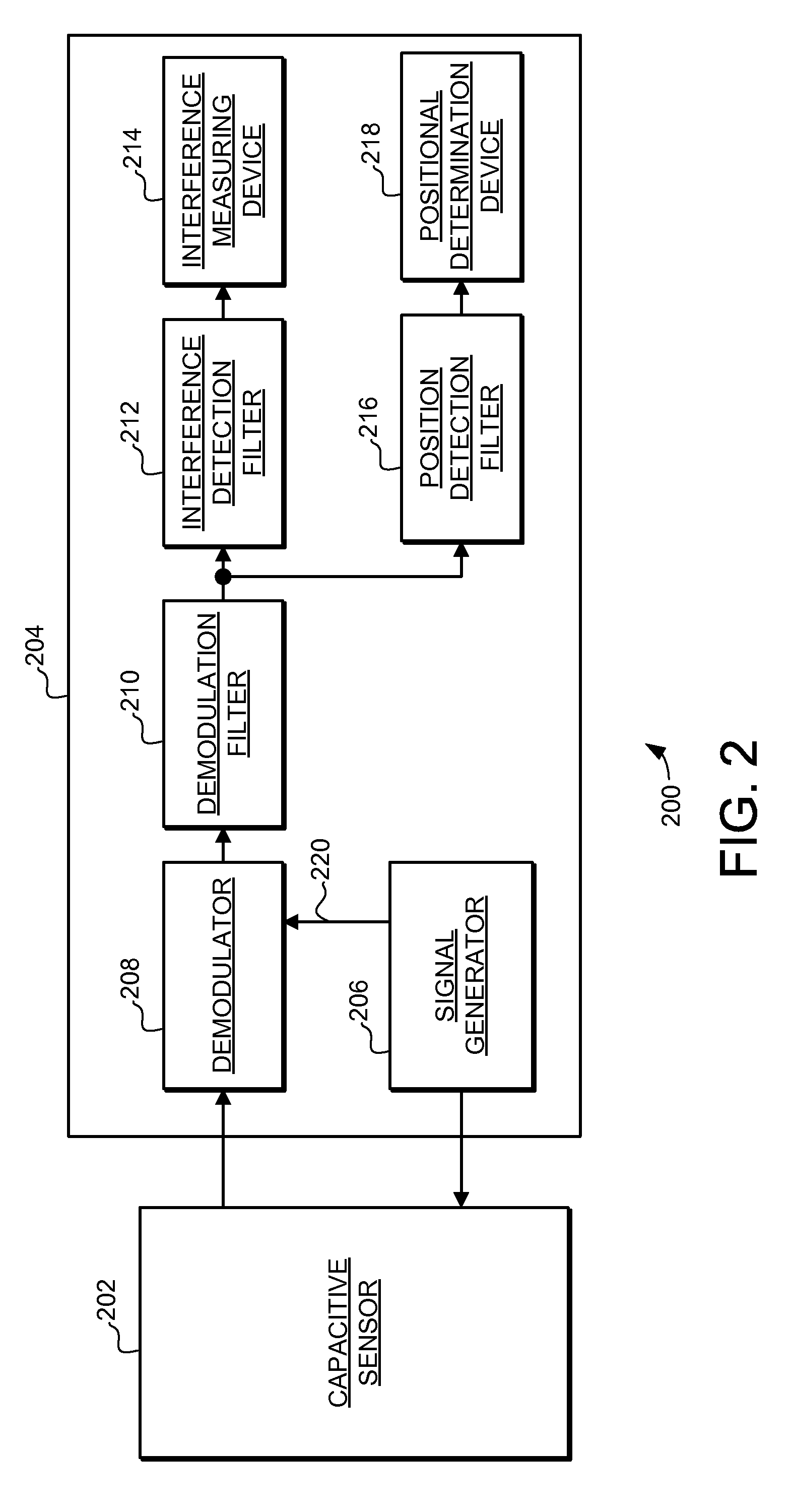
[0017]The embodiments described herein provide a system and method for detecting interference in an output of a capacitive sensor device. In accordance with the embodiments, a signal generator is configured to apply a carrier signal to the capacitive sensor device, and the capacitive sensor device is configured to modulate a carrier signal to produce sensor outputs in response to the user input. The carrier signal is switched between a plurality of phases at a switching rate. The result of the carrier phase shifting is that effects of interference in the output signal are broadened in frequency. An interference detection filter is configur...


PUM


Abstract

A capacitive sensor device and method is configured to respond a stimulus provided in a sensing region with an output signal. A signal generator is configured to apply a carrier signal to the capacitive sensor device. The carrier signal is switched between a plurality of phases at a switching rate, where the switching rate is less than a demodulation filter bandwidth. The result of the carrier phase shifting is that effects of interference in the output signal are frequency shifted away from the effects of user applied stimulus. An interference detection filter is configured to filter from the sensor outputs at least one effect produced by the stimulus. An interference measuring device is configured to determine a level of interference in the at least one interference output. Thus, the system can detect interference in the output of the capacitive sensor device.

Description

FIELD OF THE INVENTION[0001]This invention generally relates to electronic devices, and more specifically relates to sensor devices and to systems and methods for detecting interference in sensor devices.BACKGROUND OF THE INVENTION[0002]Proximity sensor devices (also commonly called touch sensor devices) are widely used in a variety of electronic systems. A proximity sensor device typically includes a sensing region, often demarked by a surface, in which input objects can be detected. Example input objects include fingers, styli, and the like. The proximity sensor device can utilize one or more sensors based on capacitive, resistive, inductive, optical, acoustic and / or other technology. Further, the proximity sensor device may determine the presence, location and / or motion of a single input object in the sensing region, or of multiple input objects simultaneously in the sensor region.[0003]The proximity sensor device can be used to enable control of an associated electronic system. ...

Claims


Application Information

Patent Timeline
Patent Type & Authority Patents(United States)
IPC IPC(8): G01R13/00
CPCH03K17/955H03K2217/960705
Inventor HARGREAVES, KIRK
Owner SYNAPTICS INC
Features
  • R&D
  • Intellectual Property
  • Life Sciences
  • Materials
  • Tech Scout
  • Unparalleled Data Quality
  • Higher Quality Content
  • 60% Fewer Hallucinations
Learn More