
Shotgun forearm-stock shot shell carrier with hidden rail

a forearm and concealed rail technology, applied in the field of shotguns, can solve the problems of unsatisfactory achievement of shotguns, time-consuming and complicated process, rendering shotguns an impractical alternative to other firearms, etc., and achieves the effect of increasing capacity to the user, reducing process time and complexity, and reducing process tim

Active Publication Date: 2013-01-15
PULLICAR REME ALBERTO PULL
View PDF31 Cites 23 Cited by
  • Summary
  • Abstract
  • Description
  • Claims
  • Application Information

AI Technical Summary

Benefits of technology

The present invention provides a forearm stock with increased capacity for a shotgun user while maintaining a smaller grip size. A twin or multiple tube version of the invention allows for even greater capacity and also increases the overall grip size. The additional shot shell tubes are integrated into the forearm stock, located close to the host shotgun's magazine and shot shell load ramp, allowing for quick and accurate reloading. The shell outlet location of each tube is at the rear end of the forearm stock, allowing for easy and efficient reloading with shells stored only a few inches away in the invented carrier. This solution provides a more convenient and efficient way to reload the shotgun between rounds and does not require the complexity of most prior art shot shell storage and loading solutions.

Problems solved by technology

Although rapid firing and reloading capabilities have been achieved with some firearms, such as semi-automatic rifles and pistols, they have not yet been satisfactorily achieved with shotguns.
The process is both time-consuming and complicated, essentially rendering shotguns an impractical alternative to other firearms in many situations where speed loading or the use of differing load types is critical.
Each of these options involves certain problems, including low capacity, loss of speed due to the amount of friction required in the shell holder to retain shot shells during firing and recoil or during user movement, and / or the additional weight, bulk, and complexity related to non-attached speed loader solutions.

Method used


Image

  • Shotgun forearm-stock shot shell carrier with hidden rail
  • Shotgun forearm-stock shot shell carrier with hidden rail
  • Shotgun forearm-stock shot shell carrier with hidden rail

Examples


Embodiment Construction

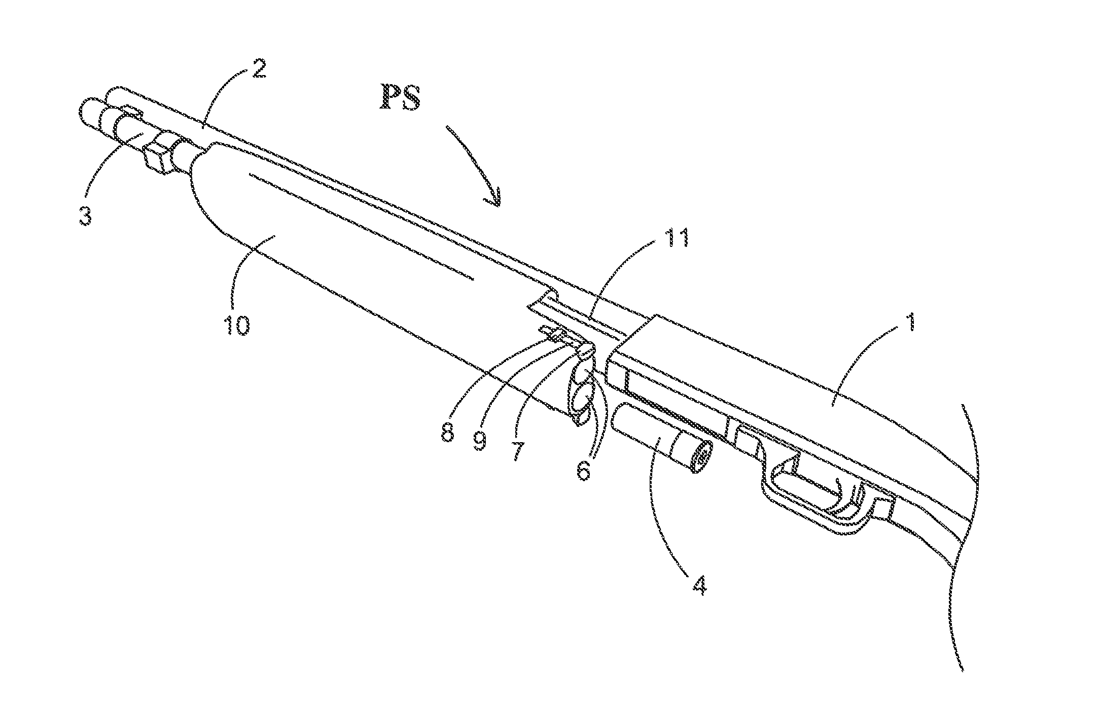
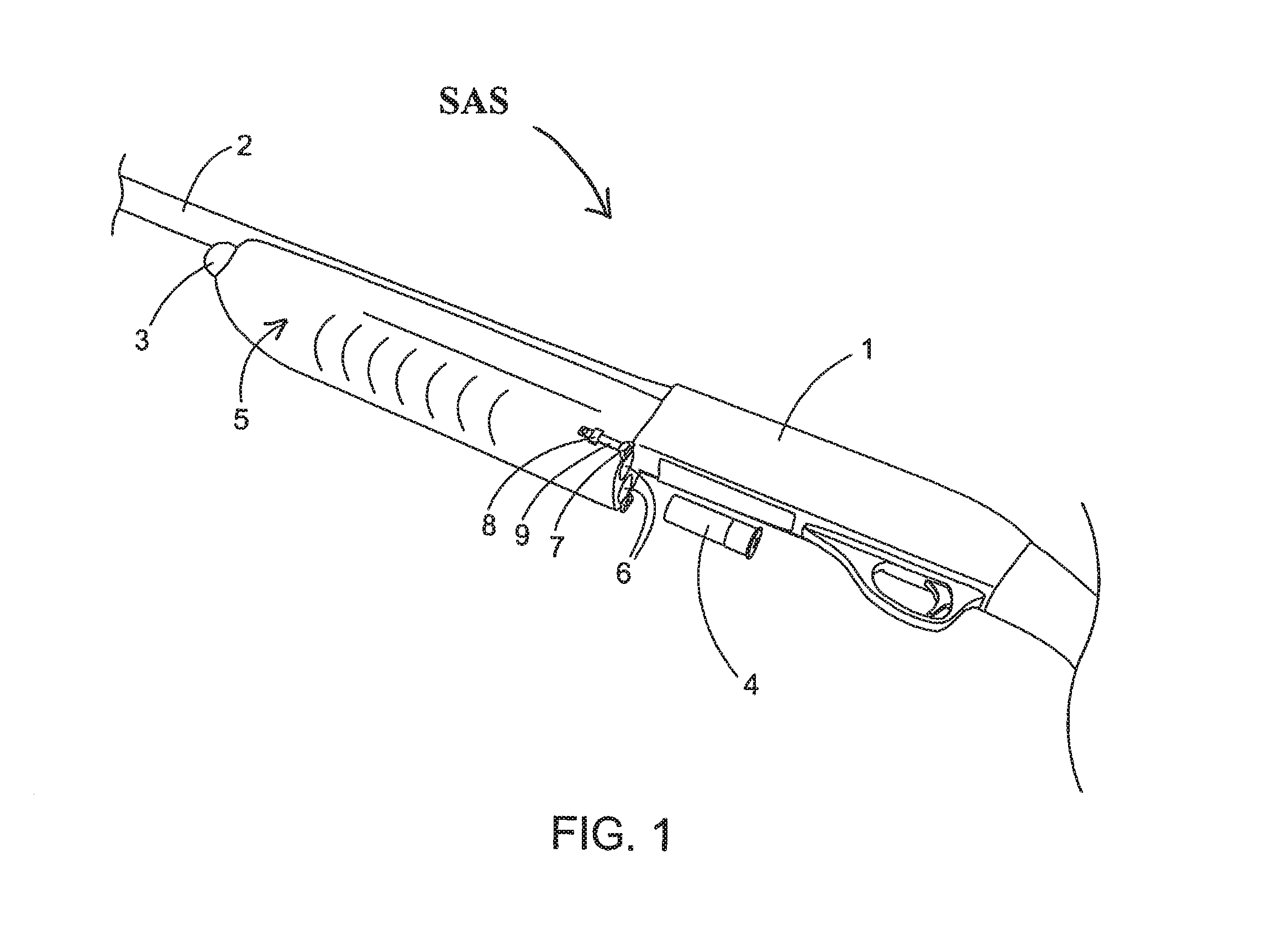
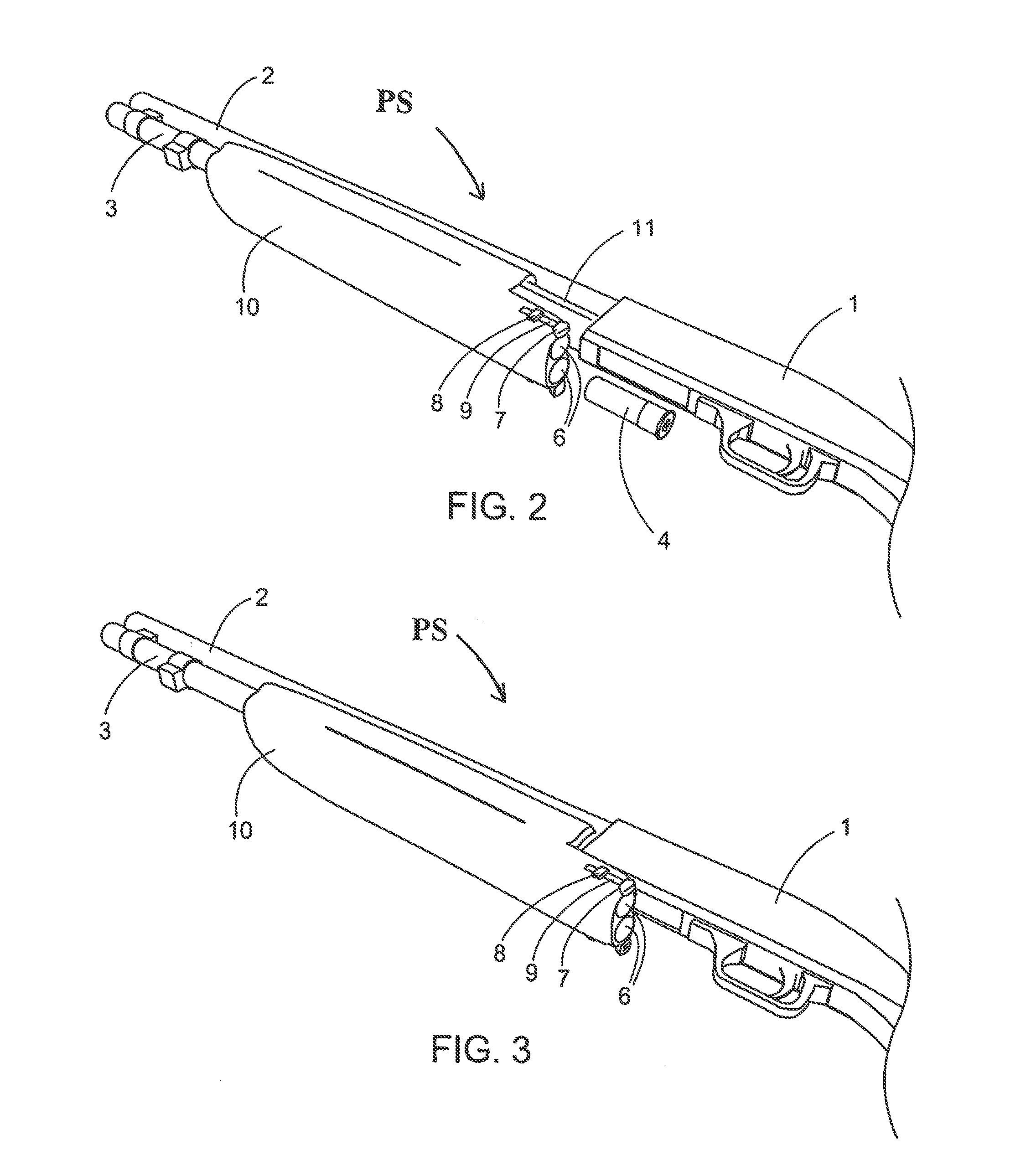
[0040]Referring now to the drawings, there are shown several, but not the only, embodiments of the invented shotgun forearm-stock shot shell carrier. The embodiments disclosed herein provide a forearm stock with integral shell carrier tubes, and the invented forearm stock with said carrier tubes replaces the conventional forearm-stock of the shotgun. The preferred forearm stock with said carrier tubes provides a structure that provides both a grip for holding the shotgun during transport or firing and the storing of additional shot shells until needed by the user. The structure for connecting to the magazine of the shotgun, the structure for use as a grip, and the structure for carrying extra shotgun shells is preferably all part of a single, integral unit.

[0041]The preferred forearm-stock shell carrier slides onto the magazine of the shotgun, in the place of the conventional forearm-stock, for example, by means of the threaded end of the magazine being removed to allow said sliding...


PUM


Abstract

A forearm stock for a shotgun includes a forearm stock main body, an integral shot shell carrier tube, disposed in the main body, an accessory rail, at the forward end of the main body, and a removable cover, adapted to cover the accessory rail. The forearm stock main body has a forward end, a back end, a contour, and an upper cavity for receiving a shotgun's tube magazine. The shot shell carrier tube is disposed below the upper cavity, and is adapted to receive a plurality of shot shells, with an opening toward the back end. A mechanism for urging the shot shells out of the carrier tube through the opening is provided, and a retention mechanism is adapted to selectively retain the shot shells in the carrier tube. The removable cover has a contour that substantially complements a contour of the main body.

Description

PRIORITY CLAIM[0001]This application is a continuation-in-part of U.S. patent application Ser. No. 11 / 602,544, filed Nov. 20, 2006, now U.S. Pat. No. 8,122,635 which claims priority from U.S. Provisional Patent Application No. 60 / 597,271, filed Nov. 19, 2005, both entitled “Shotgun Forearm-Stock Shot Shell Carrier,” the disclosures of which are incorporated herein by reference in their entireties.BACKGROUND[0002]1. Field of the Invention[0003]The present invention relates to shotguns and, in particular, to shotguns that can be rapidly loaded with ammunition.[0004]2. Related Art[0005]Under many circumstances it is necessary or desirable to rapidly load and fire rounds of ammunition from a shotgun. The ability to rapidly reload a shotgun for subsequent firing is often key to the firearm's effectiveness. For example, in police work and military applications, it is often necessary, for the user's survival, to be able to rapidly load a shotgun between firing rounds. In some sporting even...

Claims


Application Information

Patent Timeline
Patent Type & Authority Patents(United States)
IPC IPC(8): F41C23/00
CPCF41A9/72F41C7/02F41C23/16F41C23/22
Inventor PULLICAR, REME A.BENTLEY, JAMES K.
Owner PULLICAR REME ALBERTO PULL
Learn More