
Streetlight

a technology of streetlights and lampshades, applied in the field of streetlights, can solve the problems of short lifespan, low illumination efficiency, pollution, etc., and achieve the effects of efficient removal of heat generated, improved illumination and heat dissipation efficiency, and excellent

Inactive Publication Date: 2013-01-15
JINSUNG CNC
View PDF6 Cites 48 Cited by
  • Summary
  • Abstract
  • Description
  • Claims
  • Application Information

AI Technical Summary

Benefits of technology

[0013]Various aspects of the present invention provide a streetlight that can be installed by easily modifying a streetlight of the related art using its facilities in their current state and exhibits better illumination and heat-dissipation efficiency than a streetlight of the related art, so that it can light the street more brightly.
[0014]Also provided is a streetlight in which the longevity and maintenance are greatly improved such that maintenance is not required for a long time, and convenience in maintenance is greatly improved such that a lighting module can be simply replaced by detaching and attaching it using clamps.
[0019]According to an exemplary embodiment of the invention, the cover can be made of a transparent polycarbonate material, and has a flange formed on a periphery thereof with an “L” shaped cross section. A fitting recess can be formed in an inner circumference of the flange so that the fitting skirt having an “L” shaped cross section, formed on the periphery of the reflector, is fixedly fitted into the fitting recess. The heat dissipation pad disposed between the base plate and the reflector can be made of a material having excellent heat conductivity and has a size equal to the reflector. Thereby, the heat dissipation pad can be interposed and fixed between the base plate and the reflector when a plurality of fixing bolts fix the cover to the base plate by extending through the flange of the cover.
[0022]As set forth above, the base plate is mounted on the streetlight body of the related art via the clamps, and the PCBs having a plurality of LEDs and the reflective films are mounted on the base plate in order to light the street or the sidewalk by reflecting light, emitted from the LEDs, to the outside. Therefore, the streetlight of the invention exhibits better illumination and heat-dissipation efficiency than the streetlight of the related art, and has an excellent effect in that the streetlight of the related art can be modified into an improved streetlight by using its existing facilities in their current state.
[0023]In addition, since the streetlight of the invention uses the LEDs as a light source and efficiently removes heat generated during the operation of the LEDs by dissipating it to the outside, neither the light-emitting performance nor the light-emitting efficiency of the LED is lowered. Therefore, since the light-emitting performance and longevity of the LED is improved, maintenance is not necessary for a long time. When the lighting module is to be replaced, it can be easily replaced using the clamps. This provides an excellent effect in that convenience in maintenance is greatly improved.

Problems solved by technology

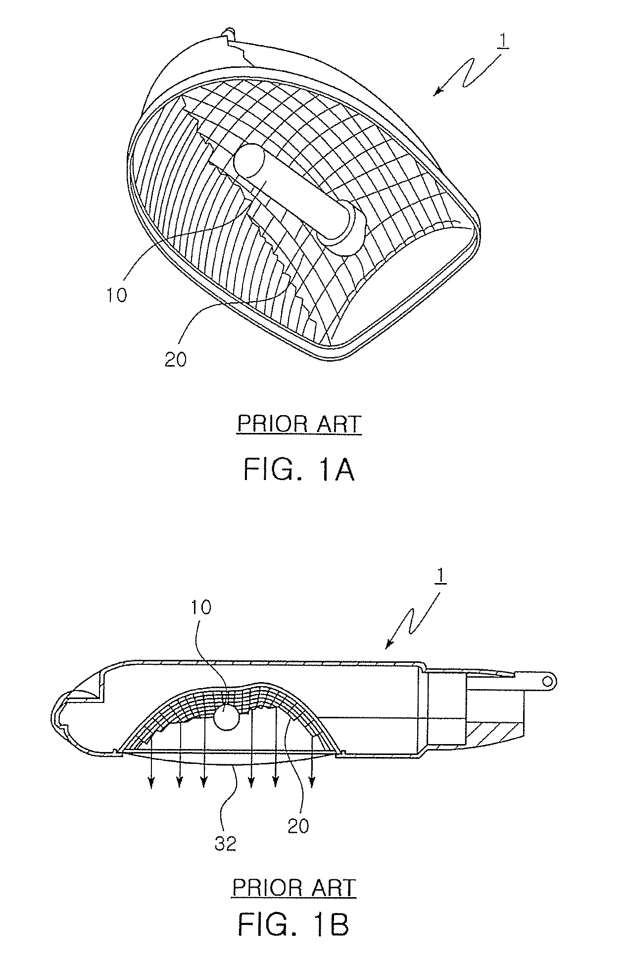
However, the streetlight 1 of the related art has drawbacks, such as low illumination efficiency, a short lifespan, and the release of pollutants when the lamp device 10 is discarded, which are attributable to the characteristics of the lamp device 10.
However, although LEDs, used as a light source, confer advantages such as excellent power efficiency and environment friendliness, LEDs have drawbacks in that their lifespan is reduced and their light-emitting efficiency is degraded when the temperature rises over the rated functioning temperature.

Method used


Image

  • Streetlight
  • Streetlight
  • Streetlight

Examples


Embodiment Construction

[0034]Reference will now be made in detail to various embodiments of the present invention(s), examples of which are illustrated in the accompanying drawings and described below. While the invention(s) will be described in conjunction with exemplary embodiments, it will be understood that the present description is not intended to limit the invention(s) to those exemplary embodiments. On the contrary, the invention(s) is / are intended to cover not only the exemplary embodiments, but also various alternatives, modifications, equivalents and other embodiments that may be included within the spirit and scope of the invention as defined by the appended claims.

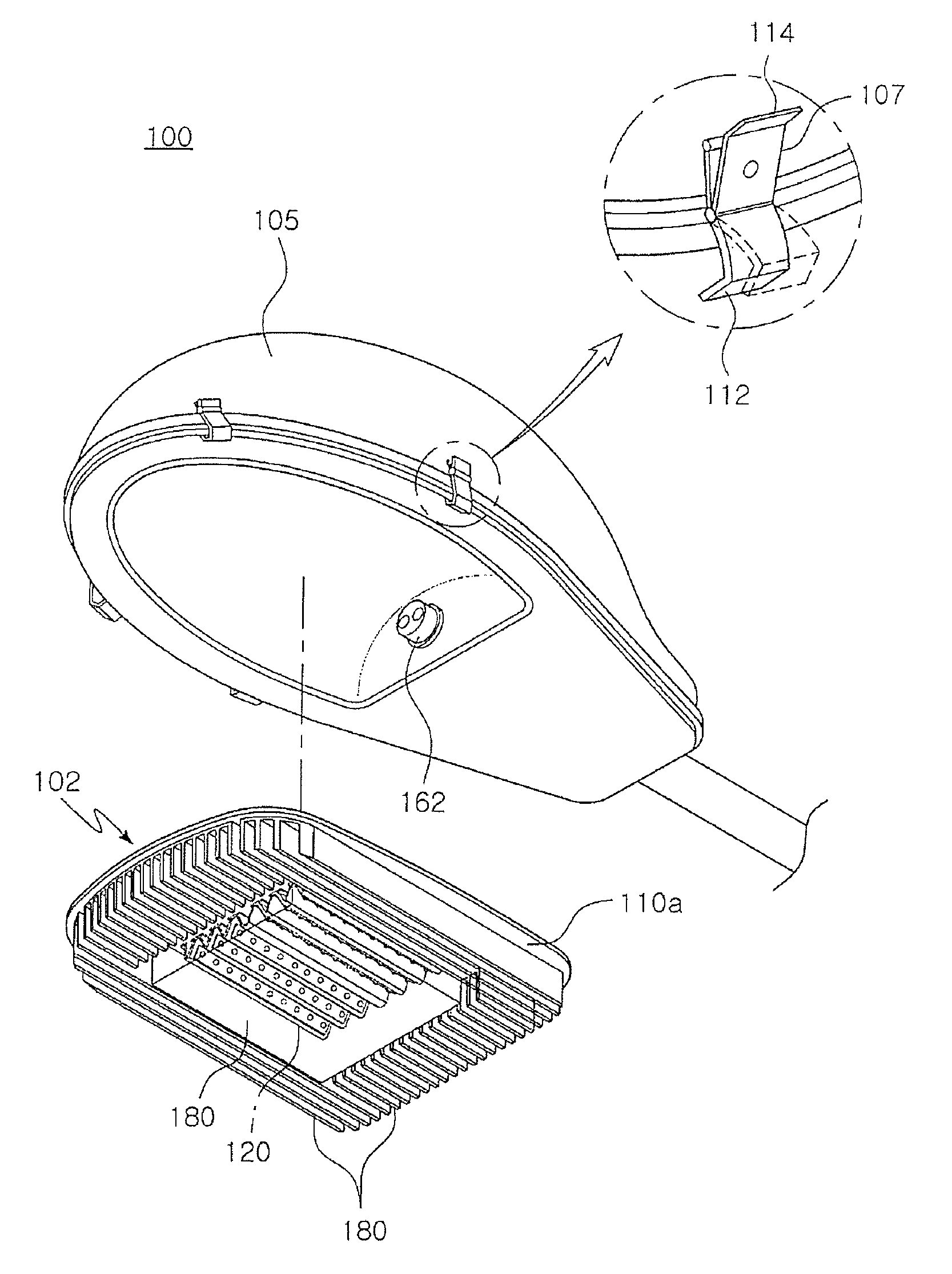
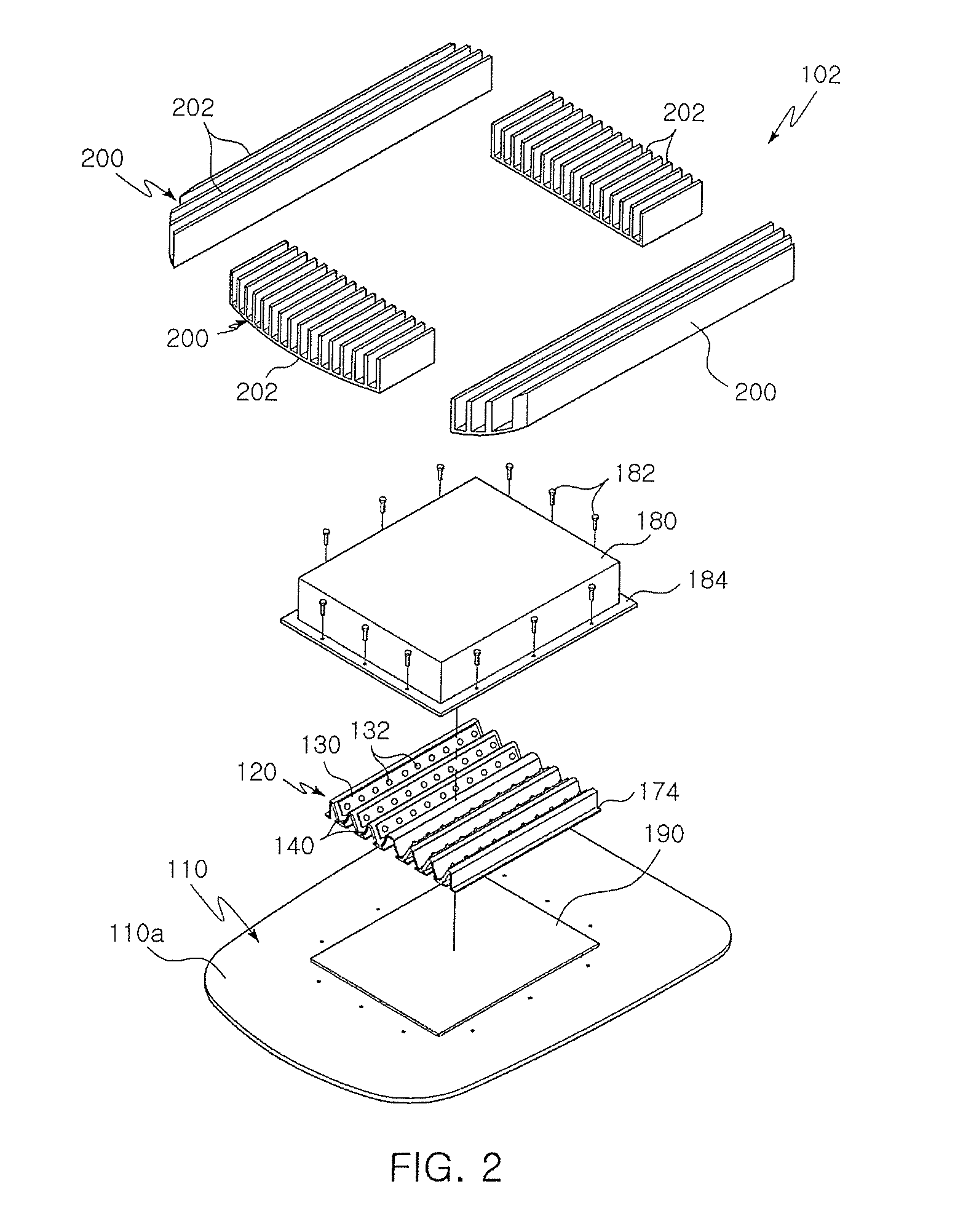
[0035]Referring to FIG. 2, a lamp device 102 of a streetlight 100 according to an exemplary embodiment of the invention has a modular mounting structure. As shown in FIG. 3A, the lamp device 102 of the streetlight 100 includes a base plate 110, which is detachably fixed to a streetlight body 105 using toggle clamps 107.

[0036]The bas...


PUM


Abstract

A streetlight installed on a street or a sidewalk in order to radiate light includes a base plate detachably fixed to a streetlight body using a clamp and a reflector fixed to one side of the base plate. The reflector has a first slope having a plurality of LEDs mounted thereon, and a second slope having a reflective film mounted thereon, the reflective film arranged opposite the LEDs. The reflector provides illumination by reflecting light, emitted from the LEDs, to the outside. A heat dissipation pad is disposed between the base plate and the reflector. The heat dissipation pad insulates the LEDs from external high-voltage EMS. A cover made of a translucent material has a recess in the central portion thereof to house the reflector therein, and fixes both the reflector and the heat dissipation pad to the base plate. Heat dissipation fins are fixed to the base plate.

Description

CROSS REFERENCE TO RELATED APPLICATION[0001]The present application claims priority from Korean Patent Application Number 10-2010-63685 filed on Jul. 2, 2010, the entire contents of which application are incorporated herein for all purposes by this reference.BACKGROUND OF THE INVENTION[0002]1. Field of the Invention[0003]The present invention relates to a streetlight incorporating a plurality of LED modules, and more particularly to a streetlight in which metal printed circuit boards (PCBs) and reflective films are arranged at predetermined intervals on a corrugated reflector, with one PCB and a corresponding reflective film arranged opposite and facing each other at a predetermined angle so that light is radiated outside, and heat dissipation fins are disposed around the reflector in order to efficiently remove heat generated by light emitting diodes (LEDs) by dissipating it. The streetlight exhibits better illumination and heat-dissipation efficiency than streetlights of the relat...

Claims


Application Information

Patent Timeline
Patent Type & Authority Patents(United States)
IPC IPC(8): F21V29/00F21V7/00F21S8/00
CPCF21S2/005F21V7/0008F21V15/01F21V17/20F21V19/001F21W2131/103F21Y2101/02Y02B20/72F21Y2115/10F21V29/767F21Y2107/00
Inventor JEONG, TAE HO
Owner JINSUNG CNC
Learn More