Elastomeric matrix composites

Active Publication Date: 2013-01-15
HRL LAB
View PDF5 Cites 89 Cited by
  • Summary
  • Abstract
  • Description
  • Claims
  • Application Information

AI Technical Summary

Benefits of technology

[0033]A more complete understanding for the elastomeric matrix composites will be afforded to those skilled in the art, as well as a realization of additional enhanceme

Problems solved by technology

That is, current elastic matrix composite materials use either particulate reinforcement or

Method used


Image

  • Elastomeric matrix composites
  • Elastomeric matrix composites
  • Elastomeric matrix composites

Examples


Embodiment Construction

[0047]In the following detailed description, only certain exemplary embodiments of the present invention have been shown and described, simply by way of illustration. As those skilled in the art would realize, the described embodiments may be modified in various different ways, all without departing from the spirit or scope of the present invention. Accordingly, the drawings and description are to be regarded as illustrative in nature and not restrictive.

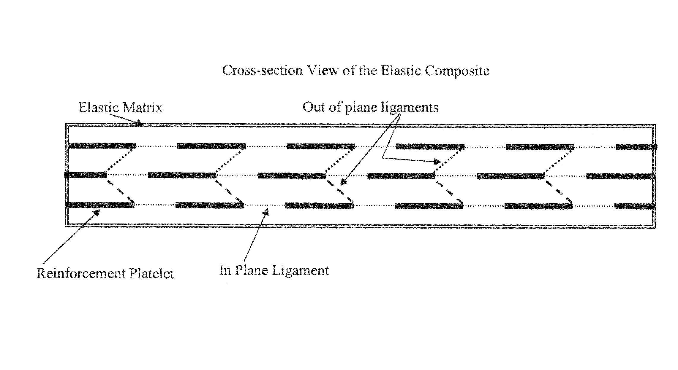
[0048]Embodiments of the present invention provide engineered microstructure composites having an elastic or elastomeric matrix with distributed rigid reinforcements. In one embodiment of the present invention, a method is provided to create large deformation materials (with uniaxial or biaxial strain limit in excess of 3%) that can have tailorable stiffness and Poisson ratio properties. That is, current elastic matrix composite materials use either particulate reinforcement or fibrous reinforcement that limits the types and control...


PUM

PropertyMeasurementUnit
Lengthaaaaaaaaaa
Fractionaaaaaaaaaa
Fractionaaaaaaaaaa

Abstract

An engineered microstructure composite having an elastic or elastomeric matrix with distributed rigid reinforcements. One embodiment of the invention provides an elastomeric composite including an elastomeric matrix, a plurality of rigid reinforcements embedded within the elastomeric matrix, and a plurality of attachments (or ligaments) connected to the reinforcements to interconnect the rigid reinforcements to each other. Here, in this embodiment, the elastomeric composite has a composite reversible strain limit greater than 3 percent (%) (or, in one embodiment, greater than 5%) due to kinematics of the rigid reinforcements interconnected by the attachments and embedded within the elastomeric matrix.

Description

STATEMENT REGARDING FEDERALLY SPONSORED RESEARCH OR DEVELOPMENT[0001]This invention was made with U.S. Government support under AFRL Contract No. FA8650-06-C-5059 awarded by the Air Force Research Laboratory (AFRL). The U.S. Government has certain rights to this invention.FIELD OF THE INVENTION[0002]The invention relates generally to an elastic or elastomeric matrix composite, and, more particularly, to an engineered microstructure composite having an elastic or elastomeric matrix with distributed rigid reinforcements.BACKGROUND OF THE INVENTION[0003]Current elastic matrix composites use either particulate reinforcement or fibrous reinforcement that limits the types and control of deformation that may be achieved. That is, these current elastic matrix composites do not generally provide the ability to engineer both stiffness and Poisson ratio (for the case of particulate fillers and fibrous fillers in particular). As such, there is a need for an engineered microstructure composite h...

Claims


Application Information

Patent Timeline
IPC IPC(8): B32B15/04B32B15/08
CPCB29C70/26B33Y80/00Y10T428/31678Y10T428/31681
Inventor HENRY, CHRISTOPHER P.MCKNIGHT, GEOFFREY P.
Owner HRL LAB
Why Eureka
Try Eureka