Integrated development environment for the development of electronic signal testing strategies

Active Publication Date: 2013-01-15
ADVANCED TESTING TECH
View PDF13 Cites 28 Cited by
  • Summary
  • Abstract
  • Description
  • Claims
  • Application Information

AI Technical Summary

Benefits of technology

[0022]A method for analyzing signals in accordance with the invention may use the graphics-based integrated instrumentation toolset having structure as described above, or may be implemented using alternative structure that is capable of performing the same or similar functions. The method generally entails generating a plurality of macros that each provides programming for at least one instrument that acts on an electronic signal, generating a plurality of different tests each including at least one of the generated macros, and storing the generated tests in a test storage device. The electronic signal is acquired, irrespective of the time at or dur

Problems solved by technology

Programming of instrumentation can be a tedious and/or complex task.
Even with thorough knowledge of signals, programming instrumentation is still a time-consuming task.
If one of these instrument classes and/or common practices is not available for the instrument, then the programming task be

Method used


Image

  • Integrated development environment for the development of electronic signal testing strategies
  • Integrated development environment for the development of electronic signal testing strategies
  • Integrated development environment for the development of electronic signal testing strategies

Examples


Example

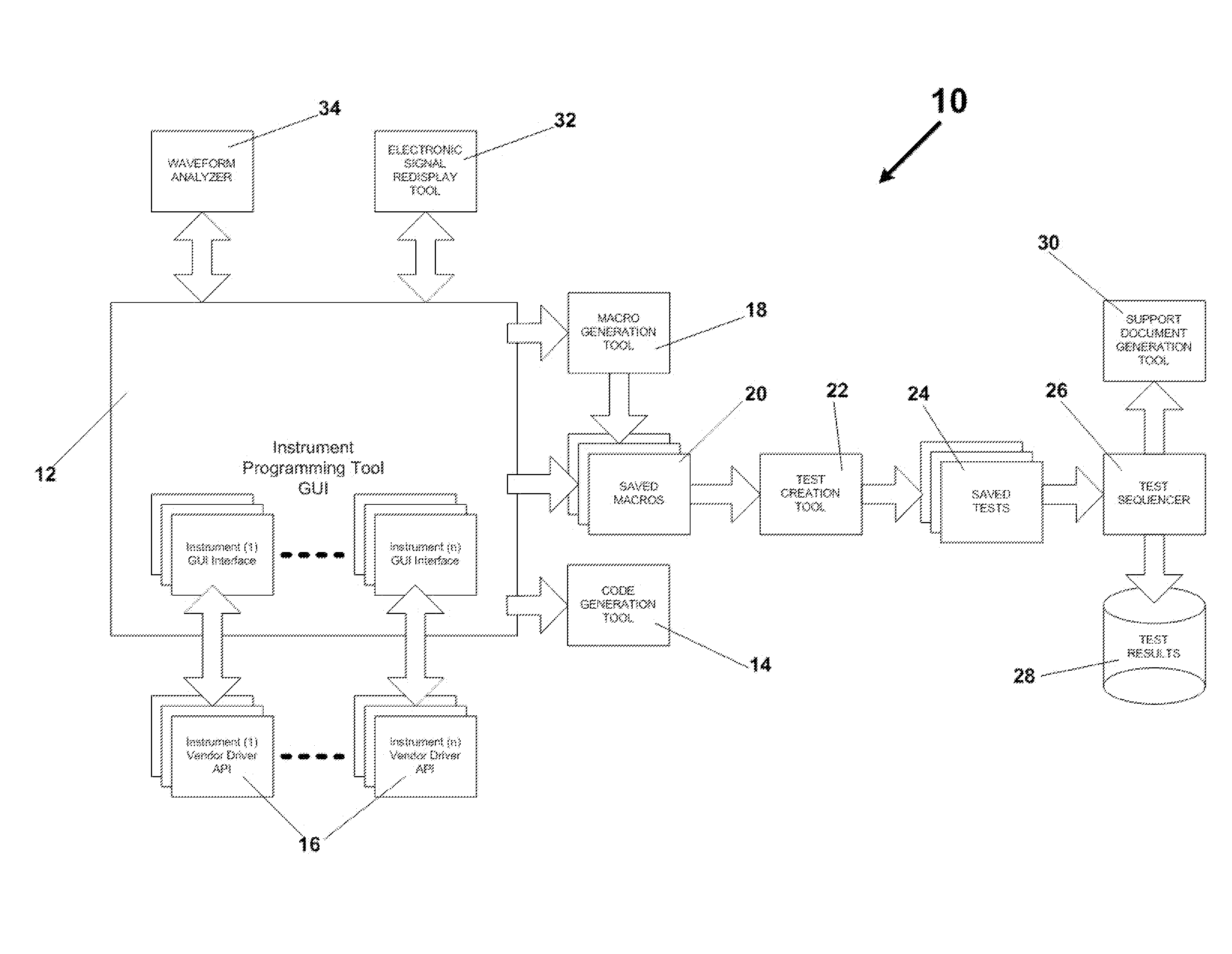
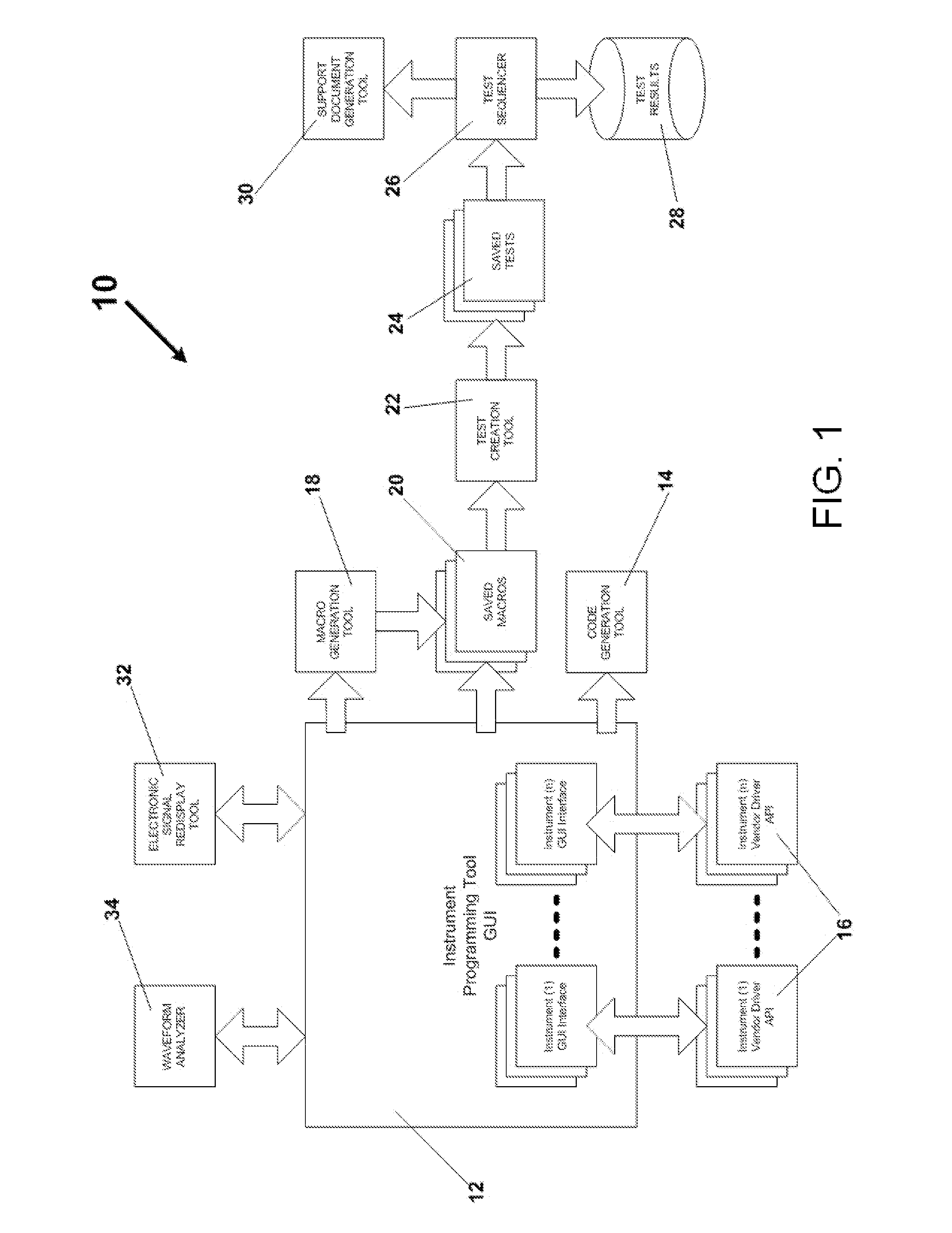
[0030]Referring first to FIG. 1, a graphical user interface 12 for an instrument programming tool (I2T) 10 in accordance with the invention provides the means to a user to program instruments interactively. The user can graphically program distinct signal characteristics or select signal standards at a click of a button of the graphical user interface (GUI) 12, or by other single or multiple action means involving the graphical user interface 12. If required, the user then can use the graphical user interface 12 to change one or many parameters of the standard. If the user has a general signal requirement, the user can also graphically program this general requirement. FIG. 1 shows a single instrument programming tool or GUI 12, it is understood though that the invention may include a plurality of GUIs.

[0031]To accomplish the capabilities of the toolset as desired in accordance with the invention, one or more virtual instrument GUIs will control the session process. This forms the b...


PUM


Abstract

Integrated application of specific CASE tools that allow a user to accomplish instrument programming and control when generating, capturing and/or analyzing electronic signals, and in doing so automatically generate automation code to replicate a desired instrument setup, acquisition, analysis and sequence control. The CASE tools include, but are not limited to, GUI instrument programming tools, an electronic signal redisplay tool, a waveform analyzer tool, automated code generation tools, macro generation tools, macro and sequence playback tools, a test creation tool, a test sequencer tool, a decision engine that may be part of the test sequencer tool, and test result data logger. A method for analyzing electronic signals that enables multiple tests to be performed after a single signal acquisition, and enables results from the multiple tests to be analyzed is also disclosed.

Description

CROSS REFERENCE TO RELATED APPLICATION[0001]This application claims priority under 35 U.S.C. §119(e) of U.S. provisional patent application Ser. No. 61 / 533,837 filed Sep. 13, 2011, incorporated by reference herein.FIELD OF INVENTION[0002]The present invention relates generally to the programming, documentation and automation of instrumentation to generate, and then capture and analyze signals using a graphics-based integrated instrumentation toolset (hereinafter referred as the I2T). The present invention also relates to a method for analyzing electronic signals in which based on a single acquisition of the electronic signal, multiple tests can be conducted on the signal and the results of the tests or measurements derived during the tests can be analyzed.[0003]The present invention relates more specifically to the presence of computer aided software engineering (CASE) tools in the integrated toolset that improve the quality, reliability, transportability and accuracy of complex tes...

Claims


Application Information

Patent Timeline
IPC IPC(8): G06F9/44
CPCG06F11/3664G06F8/34G06F11/3684
Inventor LEIPPE, WILLIAM HAROLDBIAGIOTTI, WILLIAMLEVI, ELISPINNER, ROBERT
Owner ADVANCED TESTING TECH
Why Eureka
Try Eureka