Rotatable dual magnification mirror with internal hoop illuminator and movable reflector ring

a mirror and mirror technology, applied in the field of mirrors, can solve the problems of inconvenient positioning of one's face sufficiently close to an existing flat mirror, and the general degeneration of the person's vision with ag

Active Publication Date: 2013-01-22
ZADRO INC
View PDF4 Cites 81 Cited by
  • Summary
  • Abstract
  • Description
  • Claims
  • Application Information

AI Technical Summary

Benefits of technology

[0031]According to another aspect of the invention, a mirror having first and second mirror plates of different magnification factors, e.g., 1× and 5×, located on opposite sides of a circular internal illumination source includes a gravity operated annular ring shaped light reflector plate which is concentrically located within a circular ring-shaped frame. The reflector has an outer circumferential edge which is slidably located within an annular ring-shaped channel in the inner side of the frame, and a central coaxial hole of larger diameter than the outer diameter of the illumination source. This construction enables the reflector ring to fall under the force of gravity when the mirror frame is pivoted to a horizontal position, thus positioning the reflector ring rearward of the illumination source where it is effective in reflecting li

Problems solved by technology

In some circumstances, however, it is not convenient to position one's face sufficiently close to an existing flat mirror to provide an image which is sufficiently large to enable a desired personal grooming task to be easily performed.
However, sinc

Method used


Image

  • Rotatable dual magnification mirror with internal hoop illuminator and movable reflector ring
  • Rotatable dual magnification mirror with internal hoop illuminator and movable reflector ring
  • Rotatable dual magnification mirror with internal hoop illuminator and movable reflector ring

Examples


Embodiment Construction

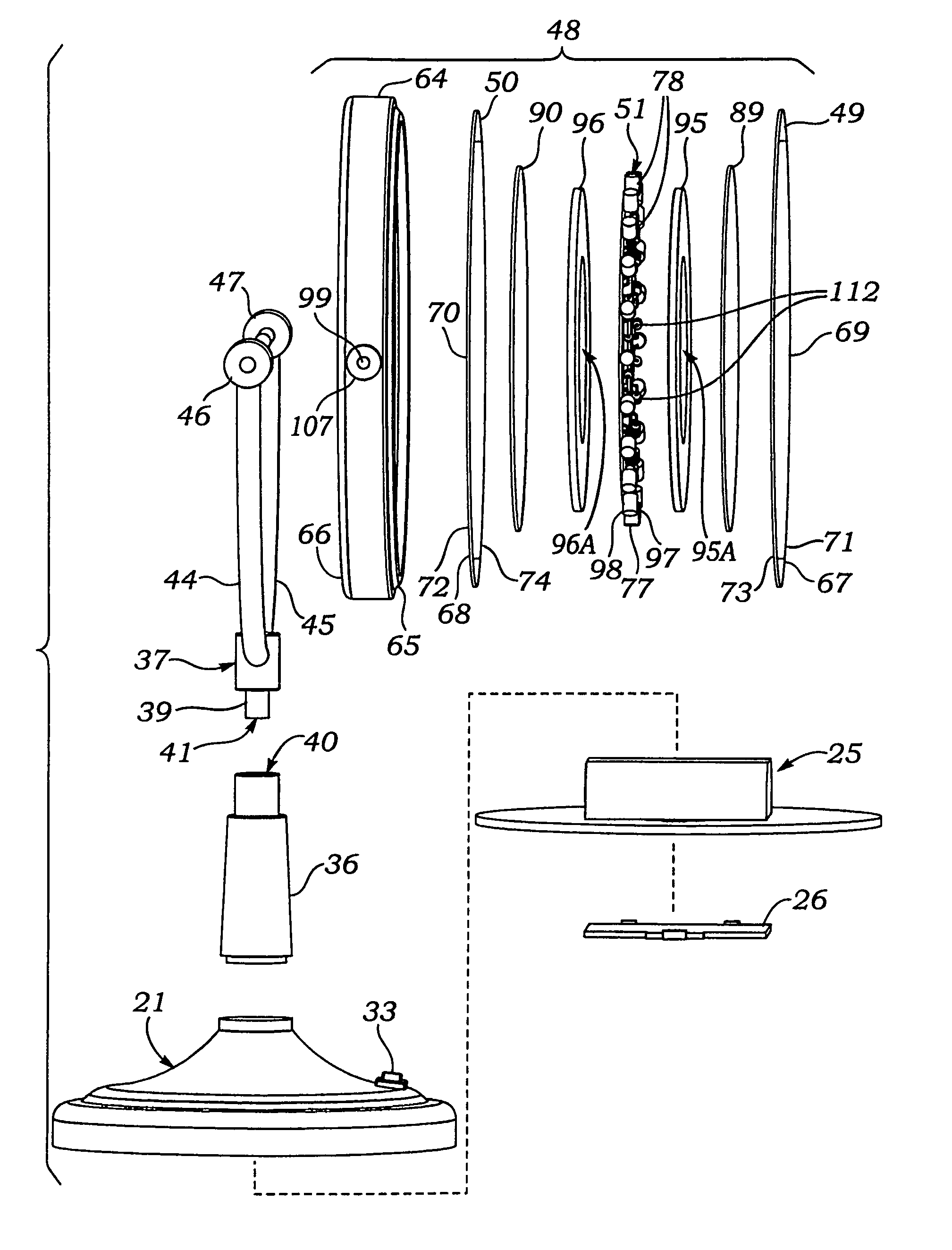
[0069]FIGS. 1-13 illustrate an illuminated continuously rotatable dual magnification mirror according to the present invention. FIGS. 14-15 illustrate details of an annular ring-shaped illumination source of the mirror shown in FIGS. 1-13. FIGS. 16-22 and 24 illustrate an alternate embodiment of an illumination source for the mirror of FIGS. 1-13. FIG. 23 illustrates a modification of the mirror of FIGS. 1-13 which uses a modification of the illumination source shown in FIG. 22. FIGS. 25 and 26 illustrate a modification of the for the figures of 1-7, in which LED light sources thereof protrude radially inwards. FIGS. 29-34 illustrate a modification of the mirrors of FIGS. 1-7 which includes a movable internal reflector ring.

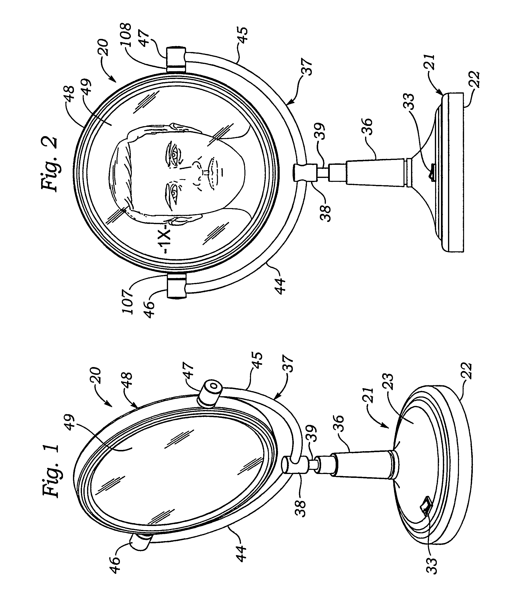
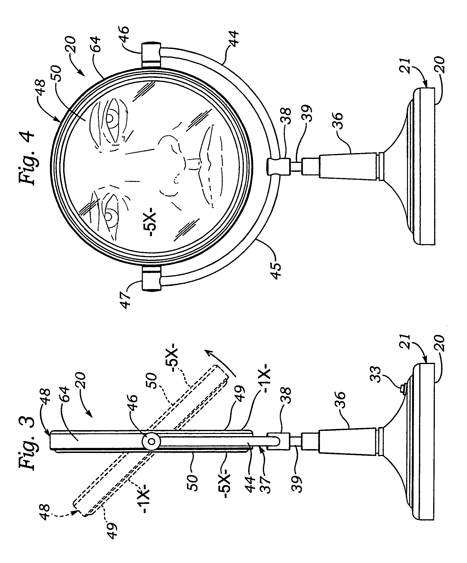
[0070]Referring first to FIGS. 1-4, it may be seen that an illuminated continuously rotatable dual magnification mirror 20 according to the present invention includes a hollow, circularly-shaped base 21 which has a flat lower wall 22 for placement on a supporting...


PUM


Abstract

A mirror includes a frame holding back-to-back a pair of reflective mirror plates having different magnification factors, each plate having a reflective central area and an outer concentric light-transmissive window area. Rotatable pivot joints supporting the frame between opposed arms of a support yoke and enable the frame to be rotated to orient a selected plate in a forward-facing use position. A hoop-shaped printed circuit board having circumferentially spaced apart light emitting diodes (LED's) protruding therefrom is located between inner facing surfaces of the mirror plates. Objects in front of a mirror plates are illuminated by direct LED rays emitted forwardly through the window areas and by indirect LED rays reflected from reflective inner facing surfaces of the mirror plates, and from the forward facing surface of a movable reflector ring within the frame which falls rearward when the frame is rotated.

Description

[0001]The present application is a continuation-in-part of U.S. patent application Ser. No. 12 / 454,865, filed on May 27, 2009, now U.S. Pat. No. 8,162,502.BACKGROUND OF THE INVENTION[0002]A. Field of the Invention[0003]The present invention relates to mirrors of the type used by people to facilitate performance of personal appearance related functions such as shaving, applying cosmetics and the like. More particularly, the invention relates to a versatile free-standing mirror which includes a base for supporting the mirror on a horizontal surface such as that of a table top, and a frame containing back-to-back mirror plates of different magnification factors, the frame being pivotably mounted to the base by a continuously rotatable joint and containing an internal flexible hoop-shaped illuminator which encircles the mirror plates and emits light forwards and backwards to thus illuminate object fields adjacent to both front and rear mirror plates.[0004]B. Description of Background Ar...

Claims


Application Information

Patent Timeline
IPC IPC(8): F21V33/00
CPCA45D42/10F21V33/004A45D42/16F21Y2101/02F21Y2115/10
Inventor ZADRO, ZLATKO
Owner ZADRO INC
Why Eureka
Try Eureka